Remote multi rotator control
This revision is from 2013/12/26 16:19. You can Restore it.
Version 2.1
Connectors
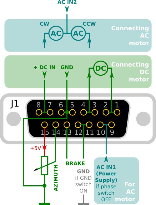
Output to rotator (DB15 female) and power inputs connector


Version 2.0

Examples
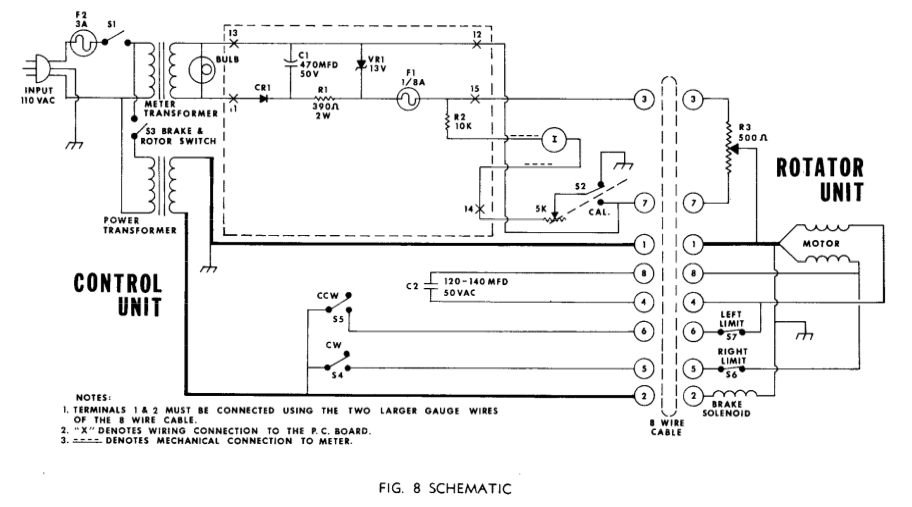
- CDE 24V~ AC

wire - description              - connected to
------------------------------------------------------------
1    - GND + center of resistor - pin 5 + 6 (DB15)
2    - Brake                    - pin 13 (DB15)
3    - resistor 500 ohm         - pin 14 through resistance (200 ohm) at pin 15 (DB15)
4    - capacitor                - C2
5    - CW                       - pin 7 + 8 (DB15)
6    - CCW                      - pin 3 + 4 (DB15)
7    - resistor                 - GND
8    - capacitor                - C2
------------------------------------------------------------
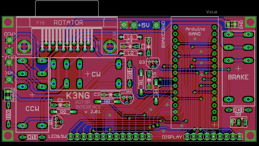
AC power for motor connected to PCB see image above, and pin 11+2 for brake
arduino pins connected
| rotator azimuth | A7 |
| CW | D6 |
| CCW | D7 |
| CW switch | A5 |
| CCW switch | A4 |
| Brake | D8 |
| Start switch | A3 |
| CW encoder | D10 |
| CCW encoder | D9 |
| LCD | 2,3,4,5,11,12 |
| Free/unused | |
| SW1 | A0 |
| LED SW1 | D13 |
| SW2 | A6 |
| SW3 | A2 |
| SW4 | A1 |
partlist
| component | value | quantity |
| PCB | 2 | |
| LCD 2x16 | 1 | |
| Arduino | nano | 1 |
| socket | DIP32 | 1 |
| D-sub 15 female angle pcb | 1 | |
| D-sub 15 male | 1 | |
| D-sub 15 male case | 1 | |
| Encoder 24imp | 1 | |
| knob black | 1 | |
| LED switch | blue | 1 |
| LED switch | green | 2 |
| strip 16 pin | 1 | |
| strip 2 pin (jumper) | 2 | |
| jumper | 2 | |
| angle strip 9 pin | 1 | |
| angle strip 13 pin | 1 | |
| Relay F1CA005V | 5V | 3 |
| L1 L2 | 100 uH | 2 |
| R9 trimr | 1K | 1 |
| Q1 Q2 Q3 | BC547 | 3 |
| C1 C2 C3 C4 C5 | 4n7/100V | 5 |
| R1 | 1k | 1 |
| R2 R3 R4 | 2k5 | 3 |
| R5 R6 R7 R8 | k51 | 4 |
| diode D1 D2 D3 D4 | x | 4 |


