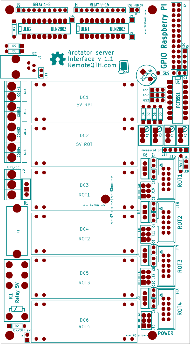
4 rotator server power board
This revision is from 2014/01/24 22:04. You can Restore it.
Part list
| K1 | Relais | ||||||||||||||||
| U2,U3,U4,U5 | L78M05 | ||||||||||||||||
| D1 | double shotky diode | ||||||||||||||||
| C1,C3,C4,C5,C6,C11 | u1 | ||||||||||||||||
| CONN1, CONN2, CONN3, CONN4 | input terminal | ||||||||||||||||
| D2,D3 | diode | ||||||||||||||||
| D4,D5,D6,D7,D8,D9 | zener diode | ||||||||||||||||
| F1 | fuse | ||||||||||||||||
| GS1, GS2, GS3 | pin array 3x1 | ||||||||||||||||
| J1, J9 | strip 10 pins | ||||||||||||||||
| J2 | pin array 13x2 | ||||||||||||||||
| J3, J4, J6, J7 | array 2 pin | ||||||||||||||||
| J5 | pin array 4x1 | ||||||||||||||||
| J14 | pin array 5x1 | ||||||||||||||||
| J15, J16, J17, J18 | pin array 5x2 | ||||||||||||||||
| R1 | resistor 4k8 | ||||||||||||||||
| R2 | resistor 3k9 | ||||||||||||||||
| R3,R4,R5,R6 | POT63YA | k | |||||||||||||||
| U1 | DIP-16__300_ELL | PCF8591 | |||||||||||||||
| ULN1,ULN2 | DIP-18__300_ELL | ULN2803 | |||||||||||||||
| J10 | conn_3x2M | ROT1-SW | |||||||||||||||
| J11 | conn_3x2M | ROT2-SW | |||||||||||||||
| J12 | conn_3x2M | ROT3-SW | |||||||||||||||
| J13 | conn_3x2M | ROT4-SW | |||||||||||||||
| DC1 | DC-DC-pcb-convertor | V RPI | |||||||||||||||
| DC2 | DC-DC-pcb-convertor | V ROT | |||||||||||||||
| DC3 | DC-DC-pcb-convertor | ROT1 | |||||||||||||||
| DC4 | DC-DC-pcb-convertor | ROT2 | |||||||||||||||
| DC5 | DC-DC-pcb-convertor | ROT3 | |||||||||||||||
| DC6 | DC-DC-pcb-convertor | ROT4 | |||||||||||||||
| C7,C8,C9,C10 | C1 | u33 | |||||||||||||||
| C2 | CP_10x21mm | G2/6.3V | |||||||||||||||
| J8 | RJ9 | I2C | |||||||||||||||
Planting plan