7ANT Controller
This revision is from 2019/05/27 22:16. You can Restore it.
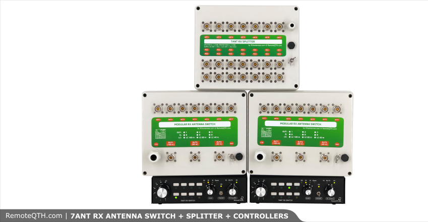
Modular 7 ANT RX switch with controller
- This controller allows you to control:
- Modular 7 ANT RX switch - link
- One antenna switch (RX) Output = One controller
- Internal BPFs (160, 80, 40m)
- Preamplifier
- Front-End RX protection
- RX way switch (TX or RX antenna)
Quick Start Guide
- How to use this RX antenna switch
- Controller description
- RX ANT WAY switch
- Connectors
- Protections
- Internal BPF and preamp PCB
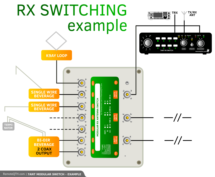
How to use this RX antenna switch
- This is almost classic antenna switch with high insulation. What is more complicated there are the dummy loads, which are there for:
- When you use any other antennas and there is no splitter, than you can leave ports open.
- Have a look here:
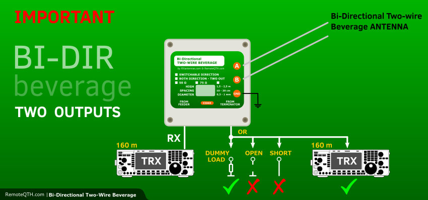
⚠ NOTE: TWO coax output beverage antenna works right only, when both ports are loaded with right impedance on the same band. It means that you cannot leave second port open or short! Also if you use first port on 160m and second on 80m than second port have to have load impedance on 160m and first port on 80m. link
⚠ NOTE: all outputs are wideband - simply BPFs work only for the dummy loads
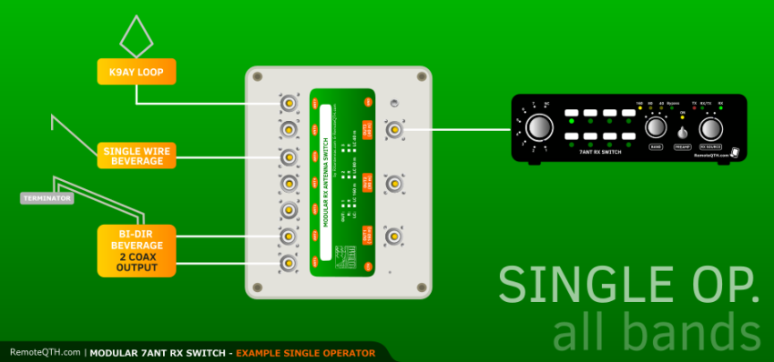
Single Operator - All bands
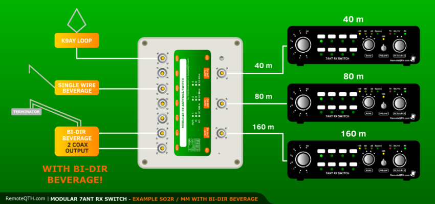
- There is one Bi-Dir beverage antenna with two coax output connected to ANT1 and ANT2 ports on the switch. If you want to obtain the best parameters of this reversible antenna, than the second port (which is not in use) must be loaded with right impedance (50 or 75 Ohm depends on design)
- The rest ANT ports on the switch are used for another RX antennas like loops, classic single wire beverage etc. This ports can stay OPEN.
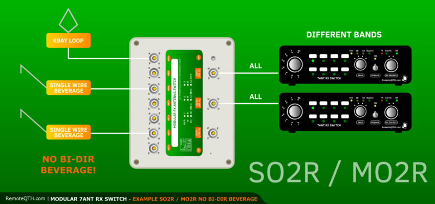
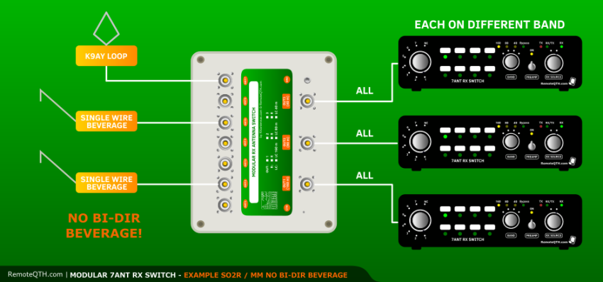
Single Operator 2 RX (SO2R) / Multi Operator 2 RX
- There is NO antenna which need dummy loadfor right work. So all ports can stay OPEN = Jumpers are disconnected.
- All OUTPUTs are ALL bands so you can use controllers on ALL bands too.
⚠ Do not use controllers on THE SAME band. This is not recommended - use two switches and middle splitter.
jumpriky *************
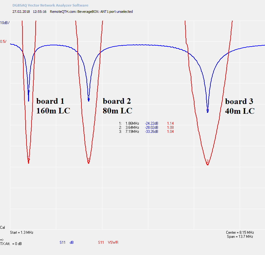
FIRST board (with 160m LC)
- This is SWR on the ANT port which is NOT used. Jumpers are configured to: LC and 50Ohm.
- You can see that the antenna port has got good SWR only on 160m. Rest FQ are on High Impedances...

FIRST (with 160m LC) + SECOND (with 80m LC) + THIRD (with 40m LC) BOARDS
- All three boards are connected.
- Jumper setting is: LC + 50Ohm
- You can see nice SWR on that three bands.
- You can imagine it like the antenna is looking into almost 50Ohm impedance.
- For Bi-Dir beverage with two coax output it means, that if the antenna port on some band is not used, dummy load is connected and antenna works like it should.
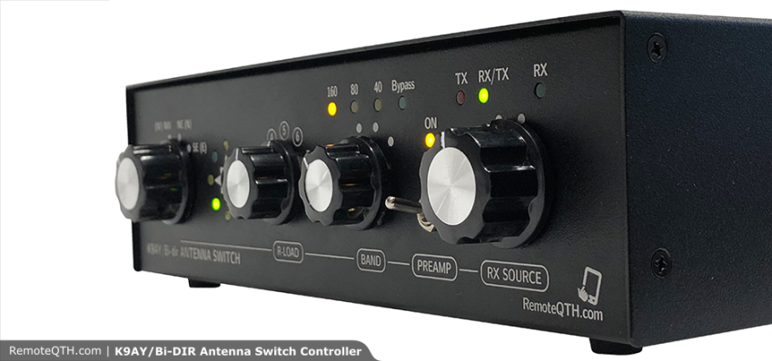
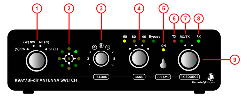
Controller description
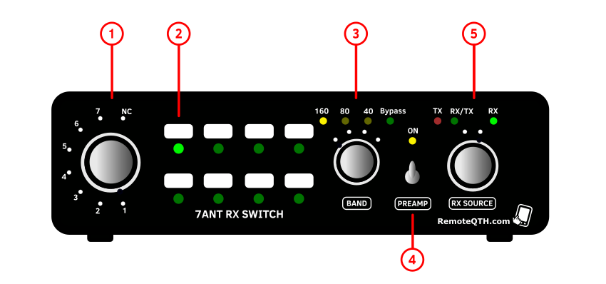
- 1 - Antenna port switch: 1 to 7 and OFF
- 2 - Antenna port LED indication
- 3 - Band Pass Filters and Bypass (160, 80 and 40m)
- 4 - Preamplifier On/OFF with LED indication
- 5 - Fast manual switch for RX antenna (see below)
- - Red LED (TX) means PTT ON.
- - Green LED (RX/TX) means RXing from TX antenna
- - Green LED (RX) means RXing from RX antenna port
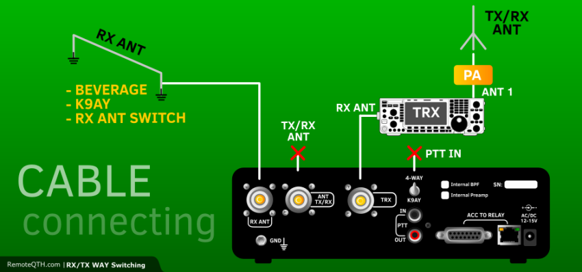
RX ANT WAY switch
- There are two ways how to connect your RX antenna controller to your TRX (RX).
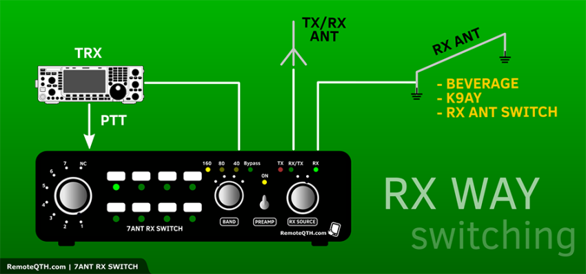
Add 1:
⚠ MUST be RX ANT ONLY PORT on TRX, no TX!!!
Add 2:
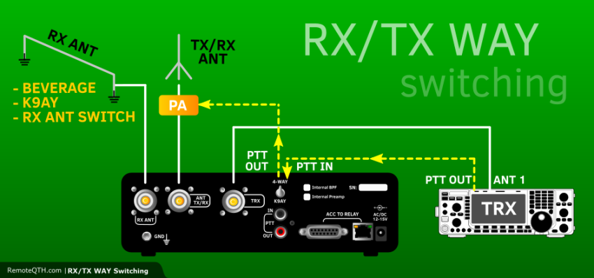
TX signal way during TXing:
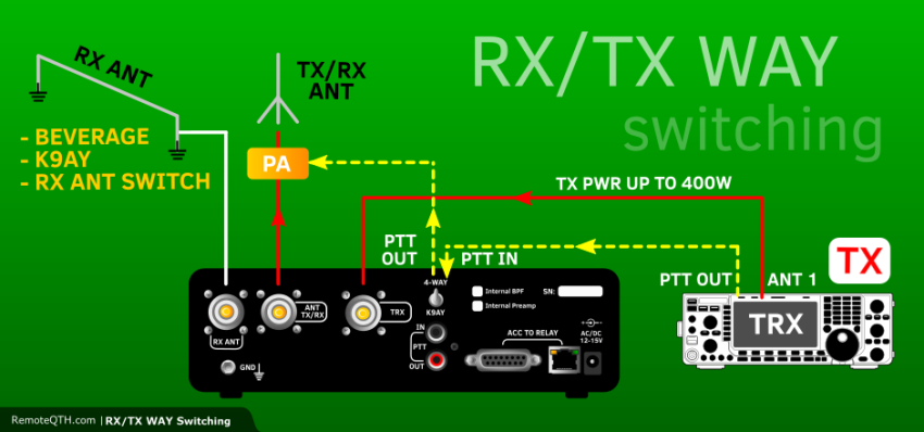
- You can use internal RX antenna switch.
- this is ideal for TRX without RX only antenna port
- also for the rest TRX for fast RX antenna switching
- switching between TX antenna and RX antenna
- If you want to use this feature you MUST use PTT IN to control relay for TX antenna!
- There is easy PTT loop on rear panel with two RCA connectors.
- PTTcontrol works only in sniffer mode.
- PTT can continue to your PA over this box.
- also when the controler is OFF
- compatible with 5V PTT logic (as OM-power PAs)
⚠ NOTE: PTT must be used!!!
- RX SOURCE knob for fast switching of the RX way
⚠ NOTE: RED LED TX must light ON when you TX PTT!!!
Protections
- There are high voltage and current protections on many places:
- At the input ANT ports in the Switch. (also in Splitter)
- At the input of the controller.
- Input and output of the internal PCB board with BPFs and preamp.
- Output to TRX. When you forget to connect PTT and transmit into RX way. The protections should do its job with the power up to 150 - 200W.
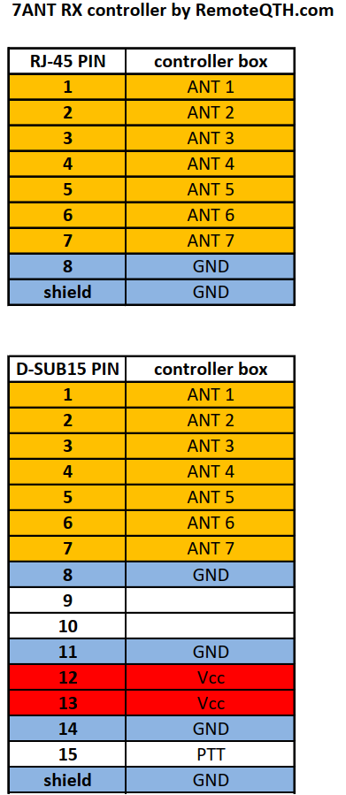
Connectors
- There are two ACC connectors
- RJ45 and SUB-D
- First 8 wires are the same.
⚠ NOTE: RJ45 is NOT LAN connection!!!
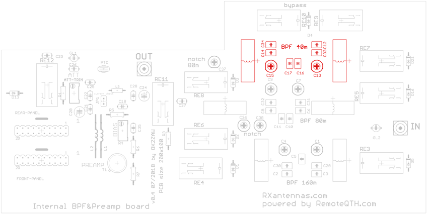
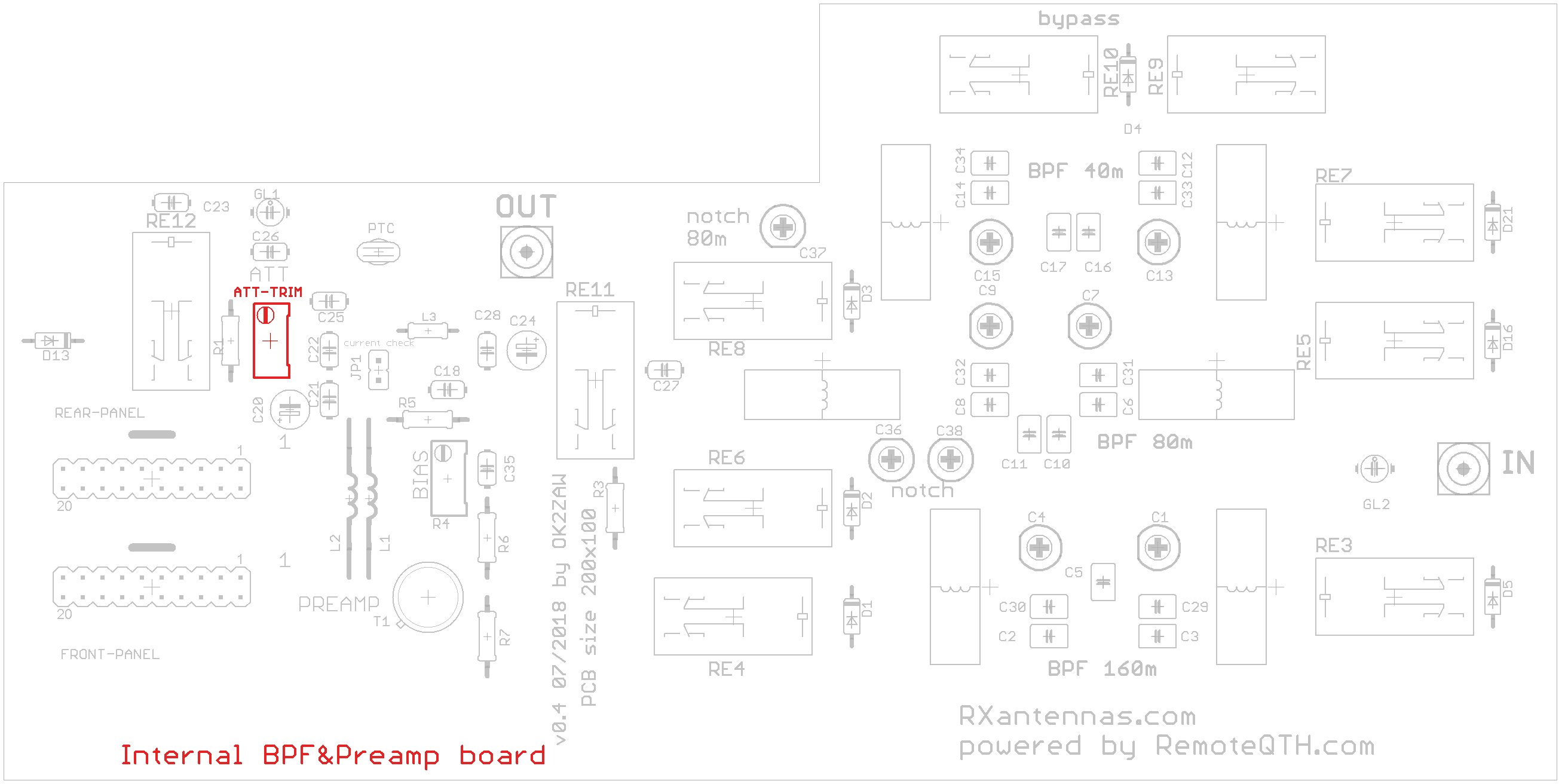
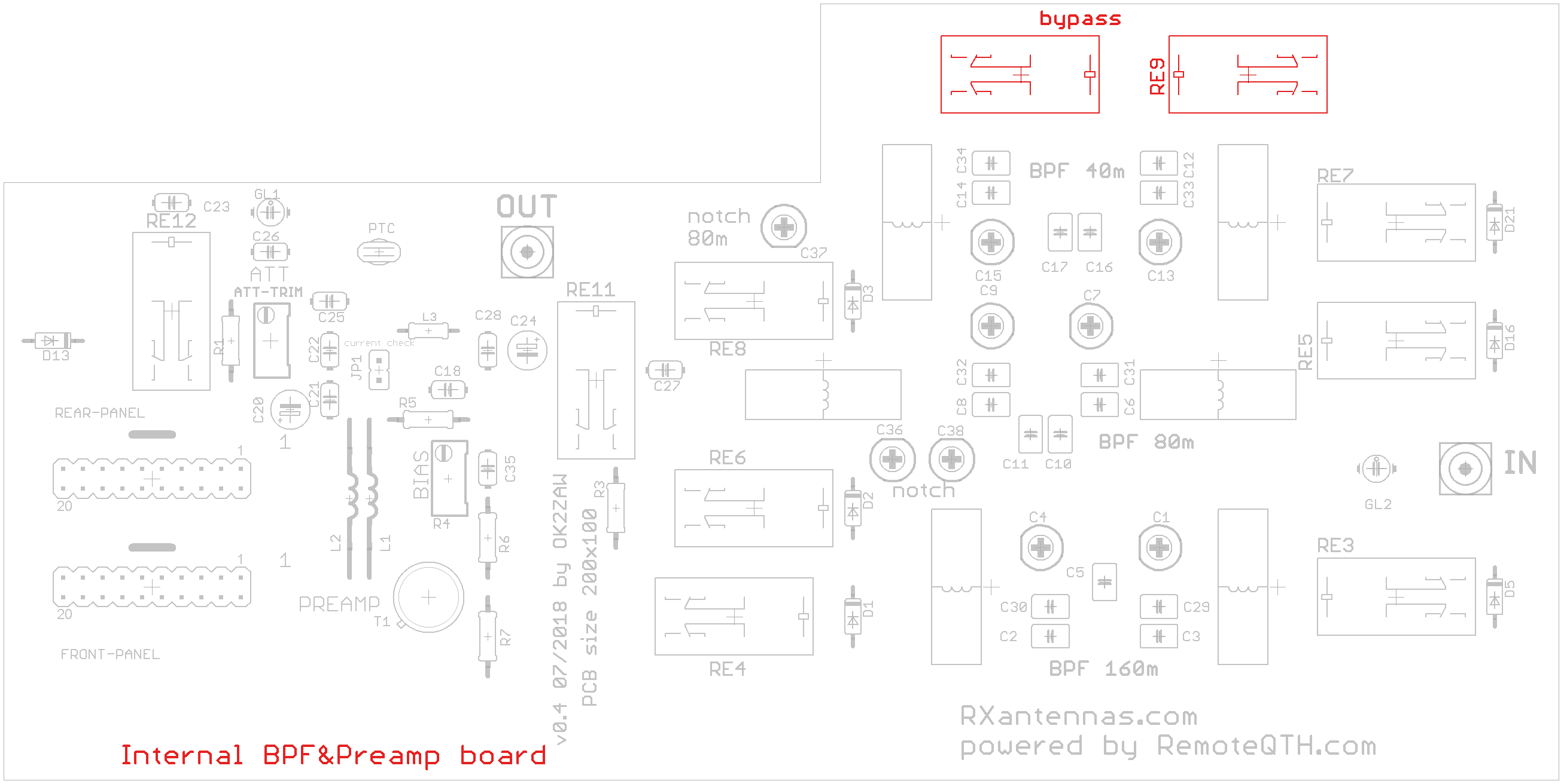
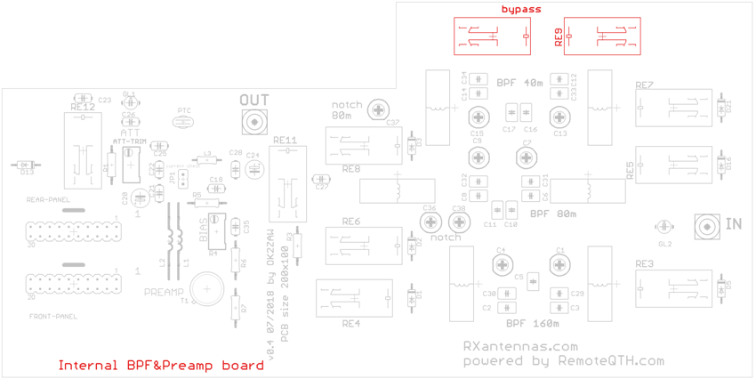
Internal BPF and preamp PCB
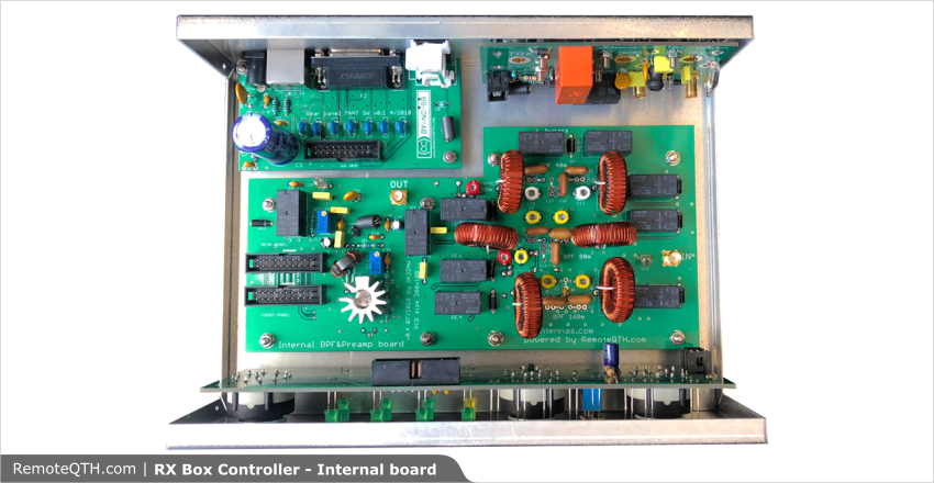
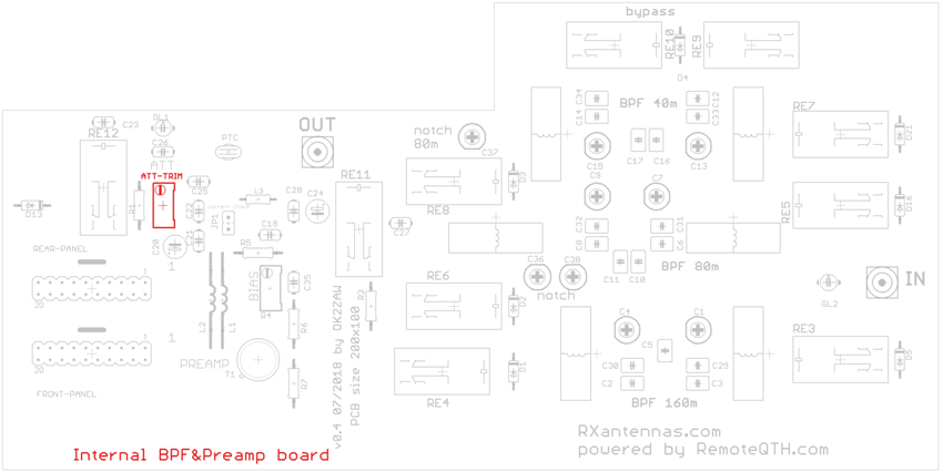
Preamplifier GAIN
- With the variable ATT you can set gain of the Preamp as you need.
- Range is 0 to 17 dB
- bigger picture
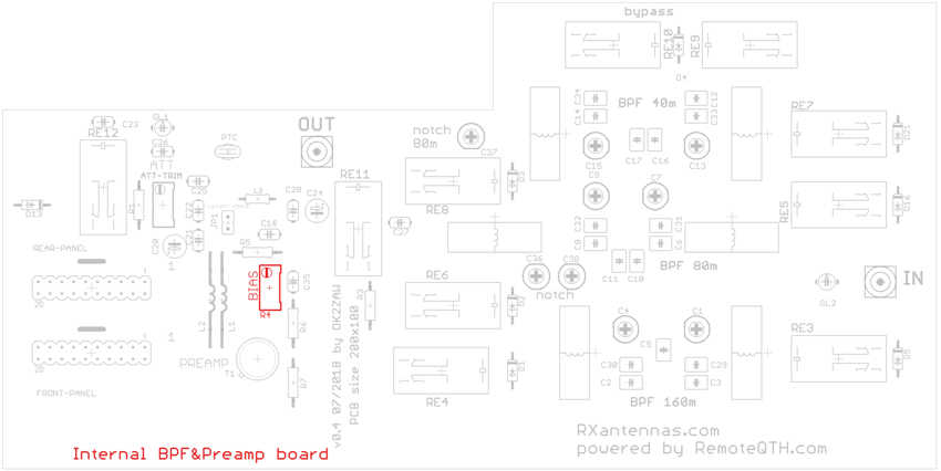
Preamplifier BIAS
- With this trimmer you can set right bias for the transistor.
- Bias vs IP3 and gain parameters are there: OK2ZAW's blog spot
- recomended bias is 60 to 85 mA for 13 V+
- bigger picture
BPF bypass
- You can use one of three BPF (160, 80 or 40m) or you can ByPass it for wideband operation
- Controller by switch on the front panel - number 4 on controller
- bigger picture
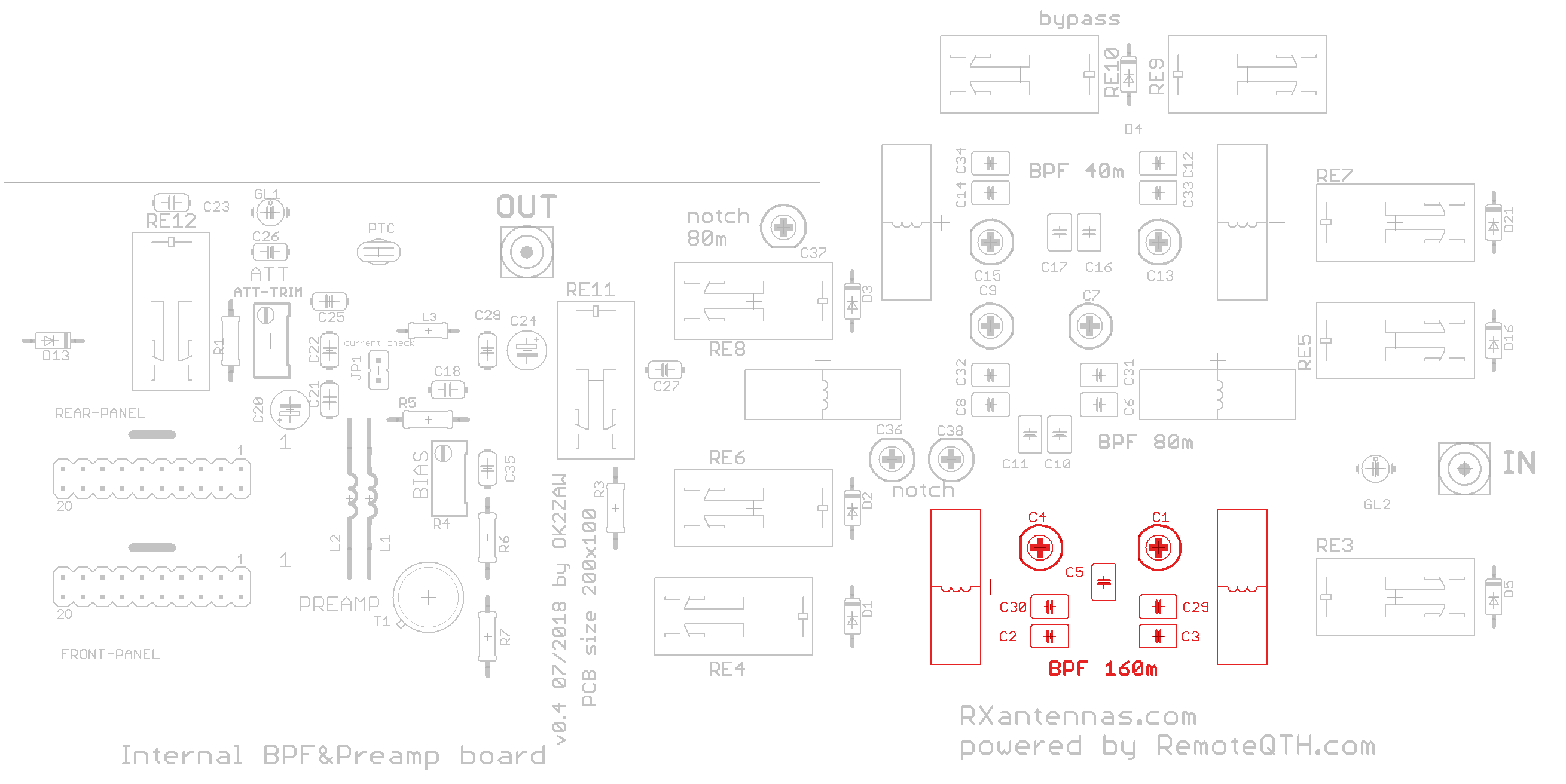
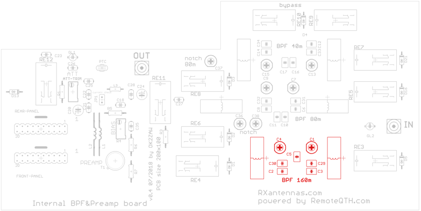
BPF 160M
- 160M BPF selected by controller.
- Switch on the front panel - number 1 on controller
- bigger picture
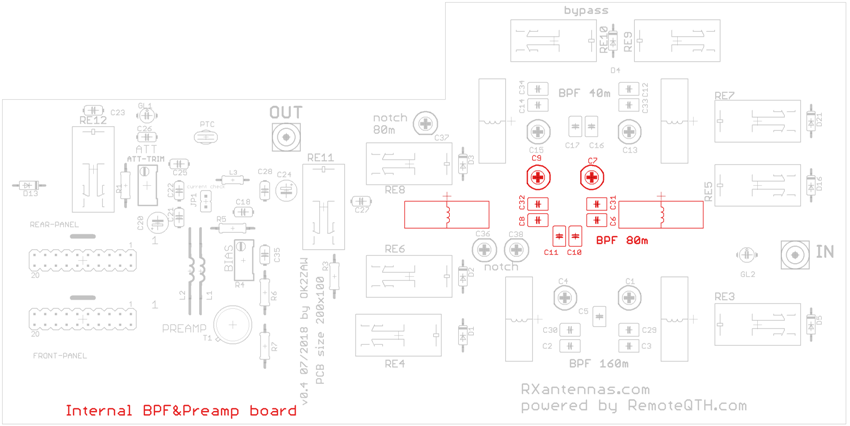
BPF 80M
- 80M BPF selected by controller.
- NOTCH filters are included, nulls 160 and 40m.
- Switch on the front panel - number 2 on controller
- bigger picture
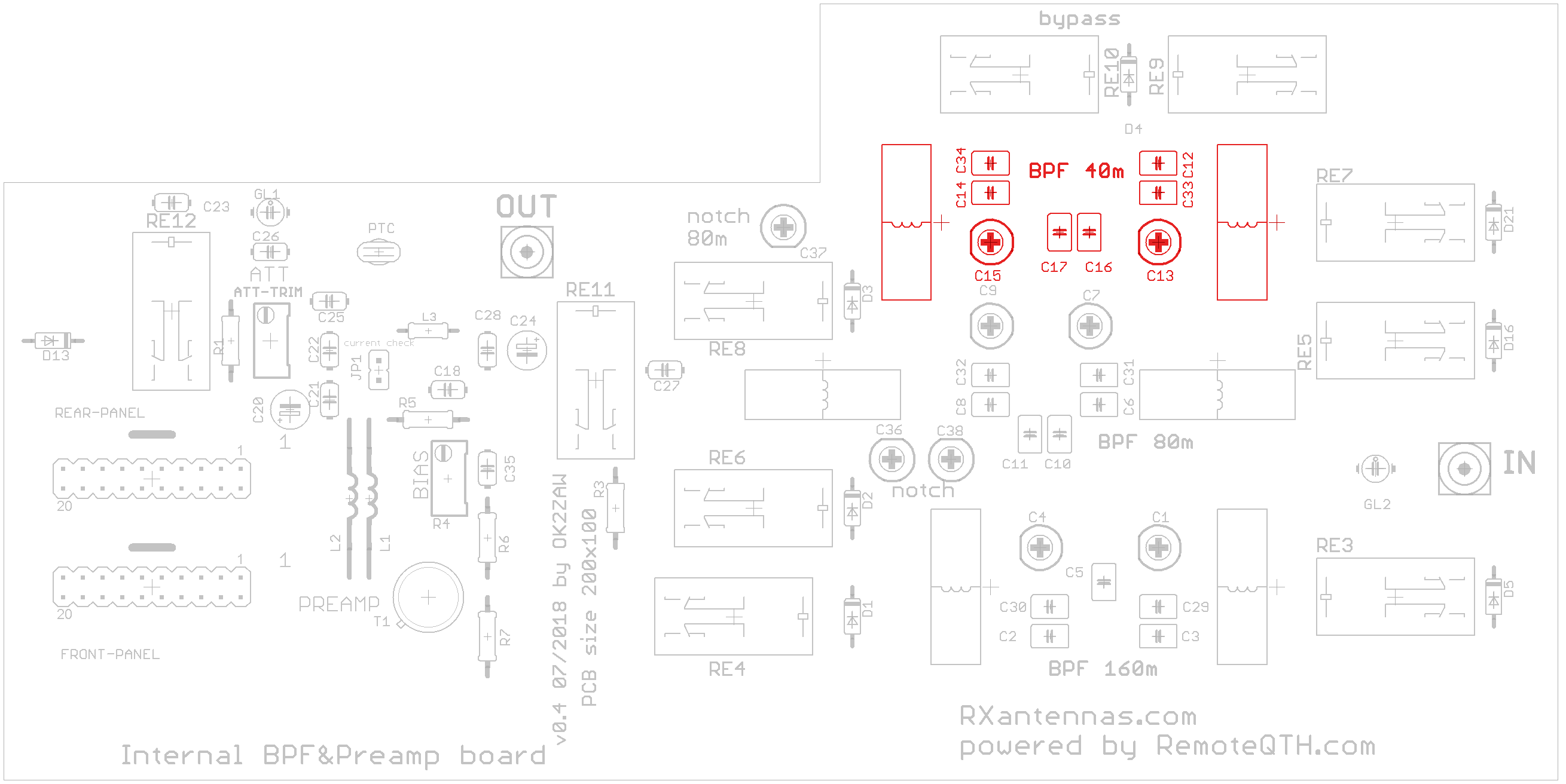
BPF 40M
- 40M BPF selected by controller.
- NOTCH filter is included, nulls 80m.
- Switch on the front panel - number 3 on controller
- bigger picture