RX antenna - K9AY loops switch with remotly VARIABLE Rload
This revision is from 2022/01/10 02:06. You can Restore it.
Current version 3.1 - Variable Rload with FIXed JUMPER
Quick Start Guide
- Youtube videos - lsn to K9AY
- K9AY LOOPs design - more size variants
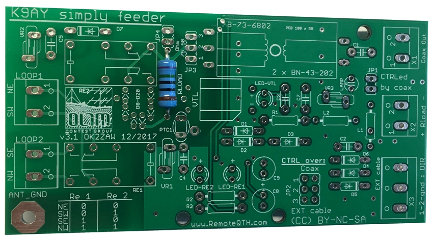
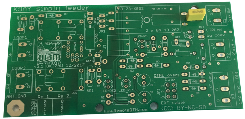
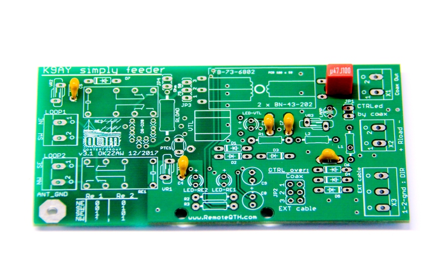
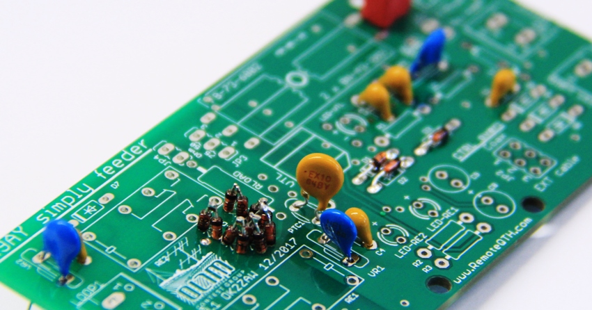
- Assembling KIT
- Schematic diagram
- Jumpers
- Common-mode coax choke
- Example of controller
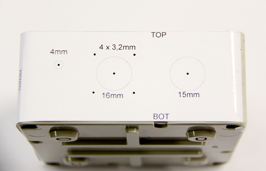
Assembling KIT
The drill drawing
Paste the drawing on the box and fix it with some tape.
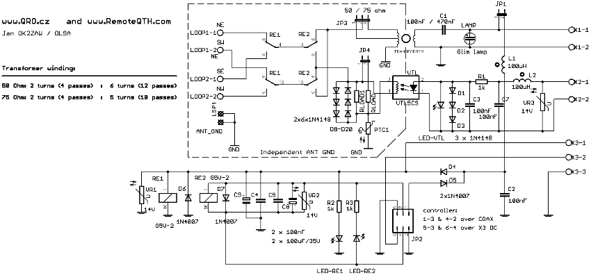
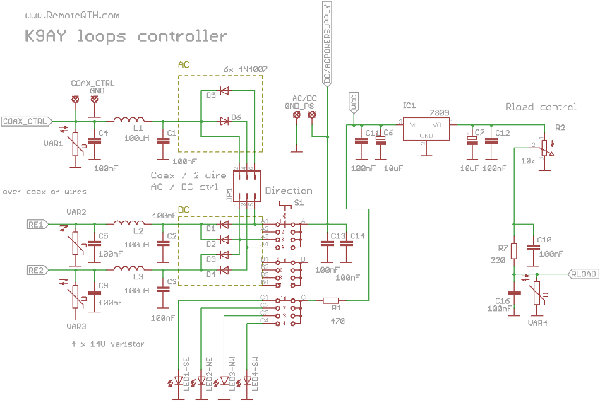
Schematic diagram
- Schematic Version 3.1
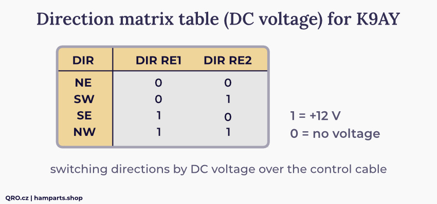
- Direction switching matrix table for DC control inputs ( apply +12V for logic 1 )
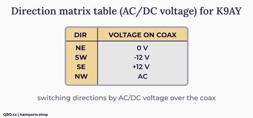
- Direction switching matrix table for AC/DC voltages over the coax
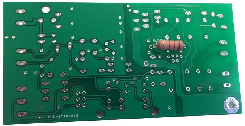
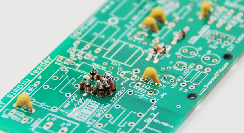
Rload resistors for VARIABLE and FIXED
- There are TWO resistors. First 1k2 in paraller to VAC and second 750 R as option for FIXed Rload - see below.
- NOTE! Solder 1k2 resistor on the botom side after the protection diodes!

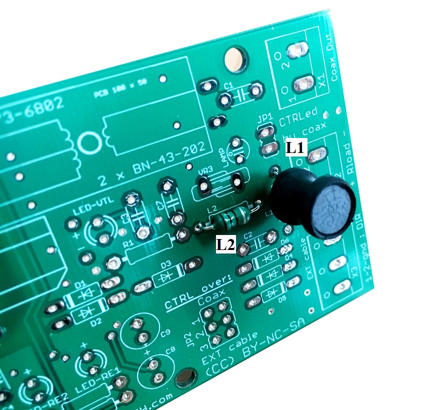
Inductors
- there are two resistors. Both are 100uH. But L1 is for higher current. L1 is black axial inructor. L2 is small resistor size green one.
Capacitors
- solder 100nF YELLOW capacitors
- some older versions do have 470nF capacitor
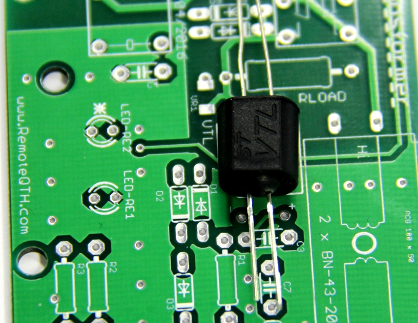
Protection diodes
- solder 6 + 6 diodes
- these diodes protect Rload resistor against high power, electrostatic etc.
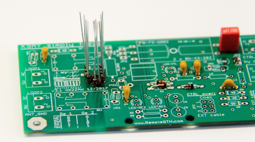
Insert PTC 100mA and rest parts
- PTC EX10
- Varistors
- rest parts
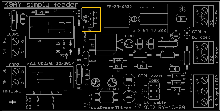
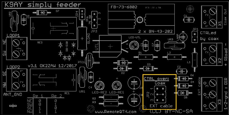
Jumpers
- By the jumper JP3 you can select 50 or 75 Ohm coax output
- Jumper JP1 must be short if you want to control direction over coax
- ⚠ NOTE: If you use external DC control, please disconnect JP1. If not, you will have DC voltage on the coax!
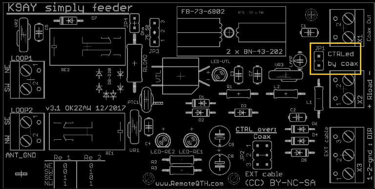
- By the jumper JP2 you can select controlling over coax or DC voltage on connector X3
- ⚠ NOTE: If you use external DC control, please disconnect JP1. If not, you will have DC voltage on the coax!
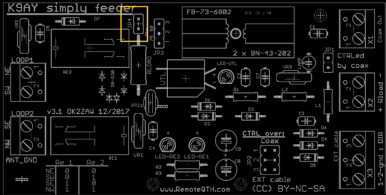
FIXed Rload !
- You can use this VARiable Rload KIT as FIXed one.
- Than you need only coax cable to control direction etc
- Conect JP4 to SHORT - and you have fixed Rload abt 460 Ohm / 4W
- DO NOT APPLY ANY VOLTAGE TO VTL!
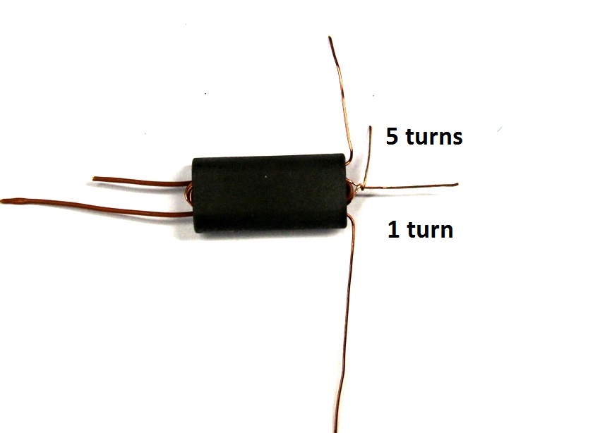
TRANSFORMERS winding - very important thing!
- for 50 ohm coax feed line : 2 turns on primar (coax) and 6 turns on secondar side (loop)
- for 75 ohm coax feed line : 2 turns on primar (coax) and 5 turns on secondar side (loop)
- In version 2.3 and higher, you can select Coax impedance by jumper JP3.
- Transformer should have 5 + 1 turns.
![]()
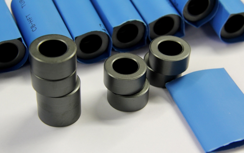
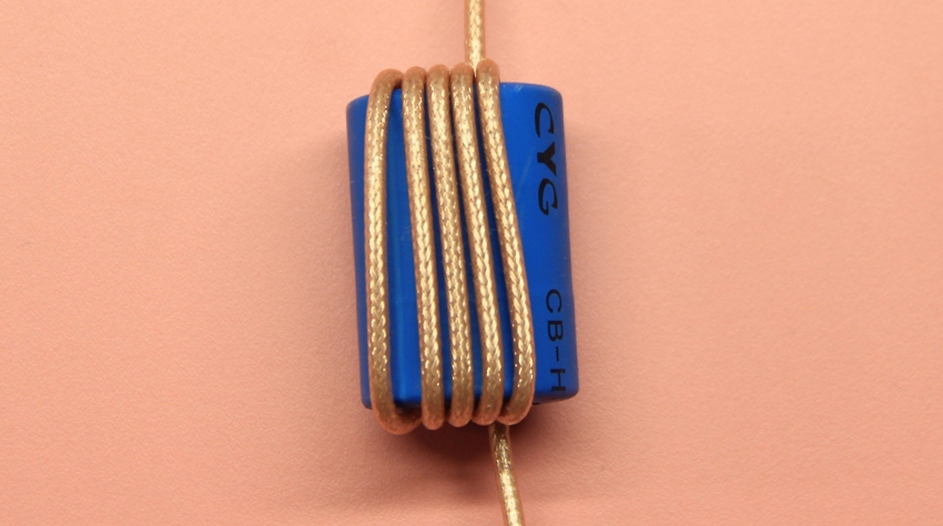
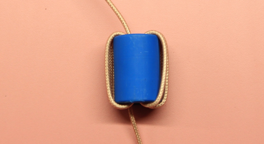
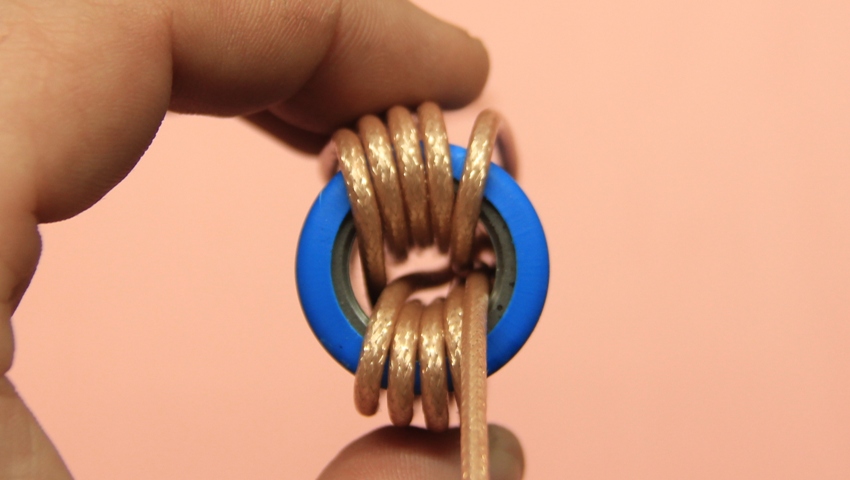
Wind the coax
- Common mode current choke construction
- Wind 4 turns on one side than cross to another side of cores and wind rest turns.
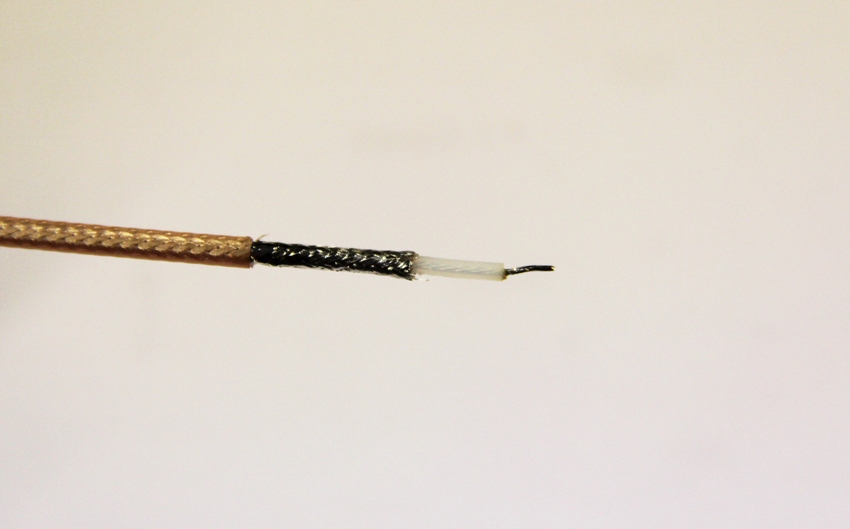
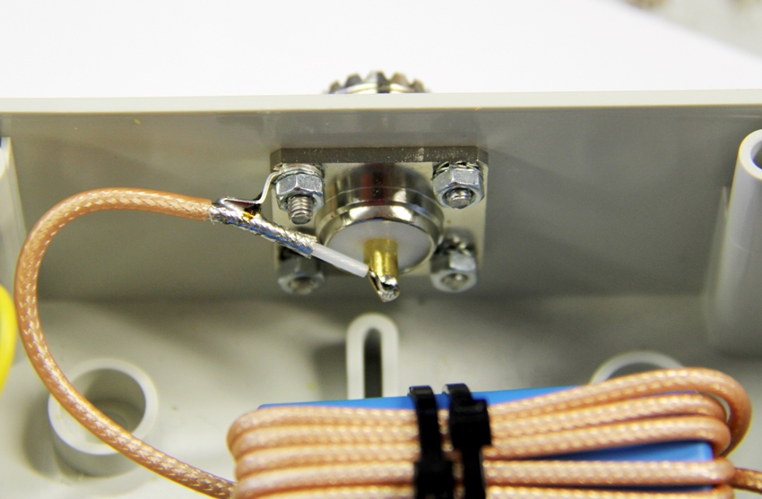
Solder the coax
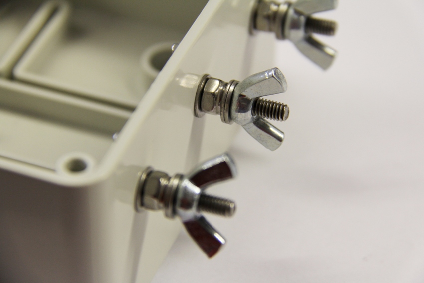
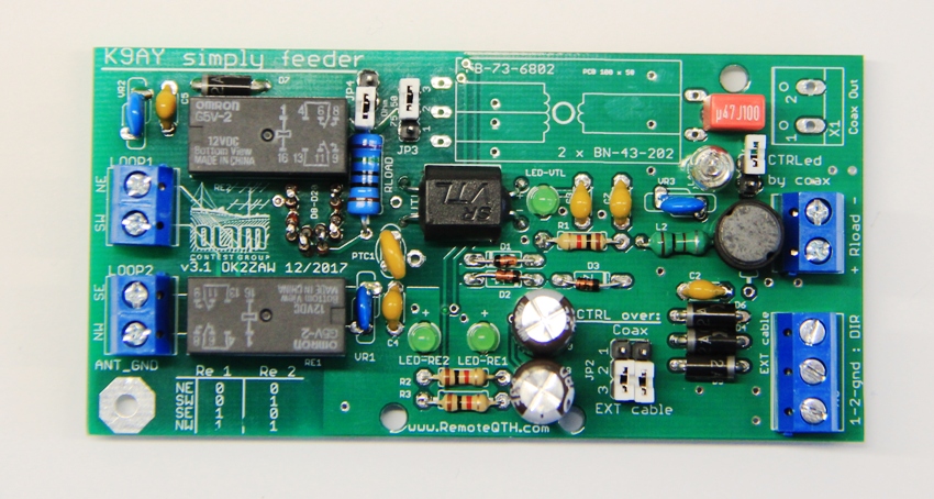
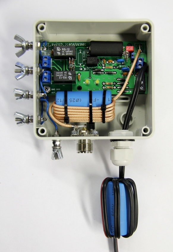
KIT - all parts assembled.
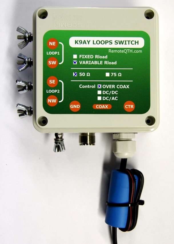
Example of controller
- Injector to coax line:
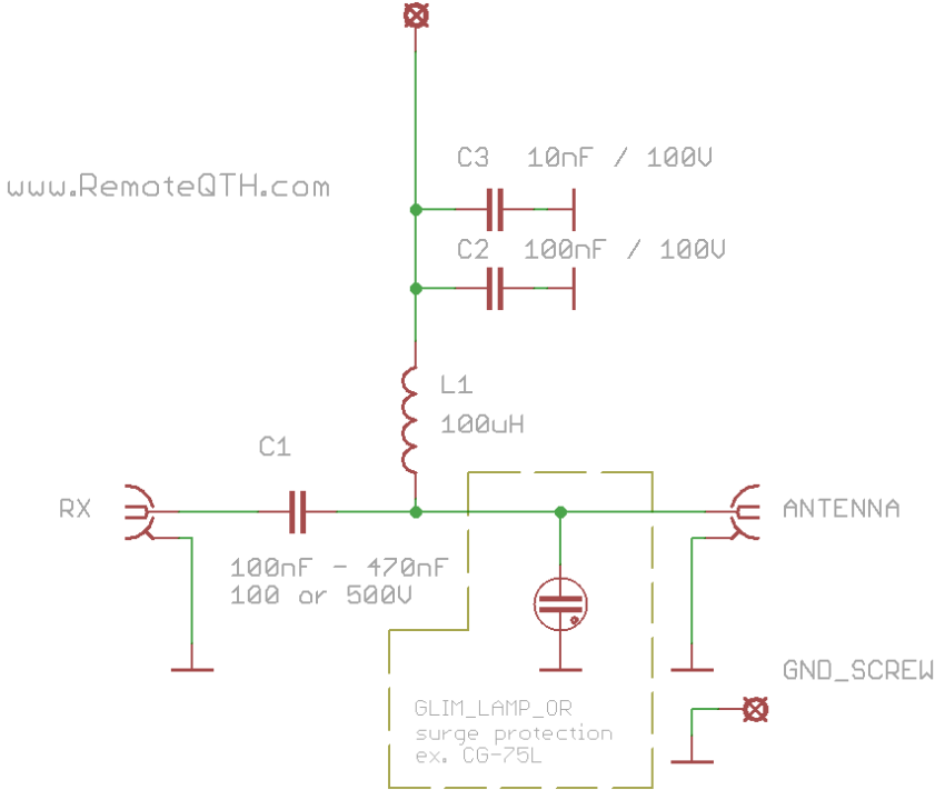
- direction and VAC Rload controller
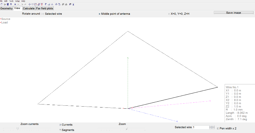
K9AY loops design example.
- It is VERY recomended to place K9AY loop antenna as far as possible from metal towers, antennas and wires. This hepls to obtain better paramaters of antenna ( directivity and noise ).
- K9AY Loop design page