Bi-Dirage beverage
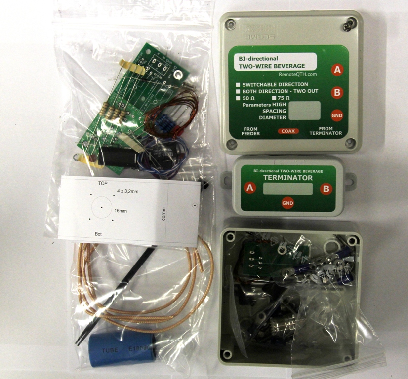
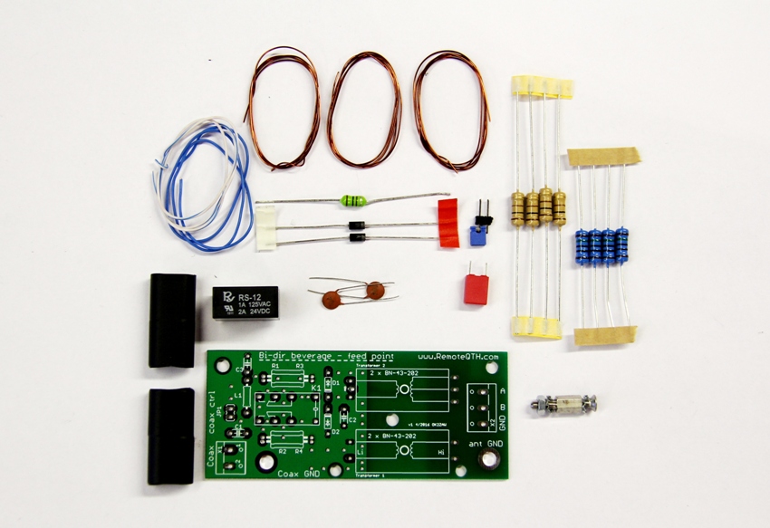
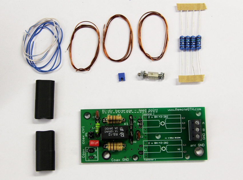
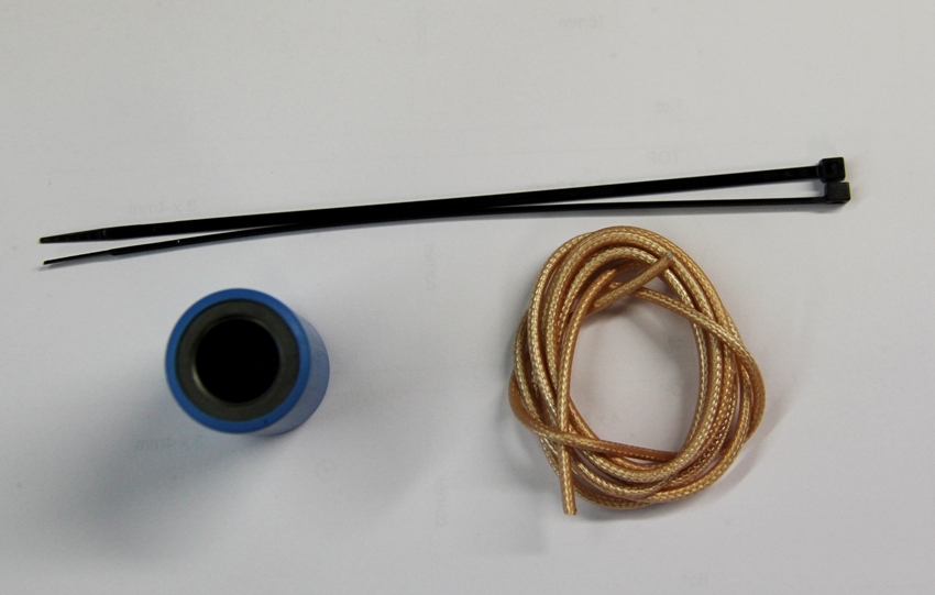
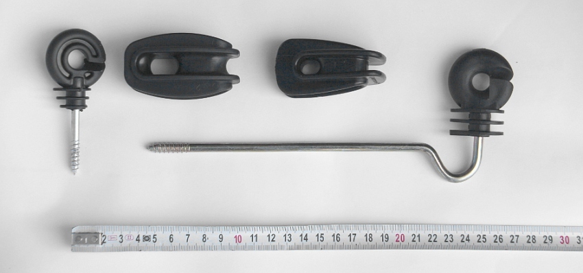
KIT - all parts you need
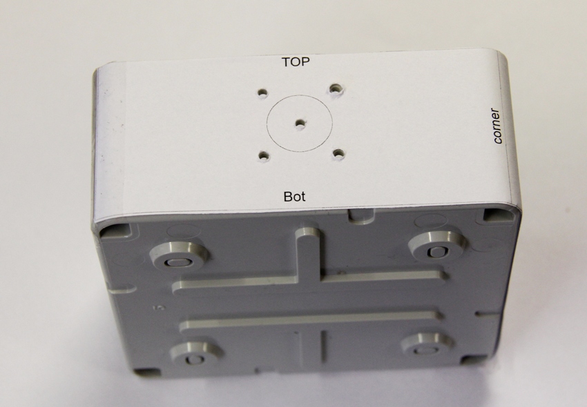
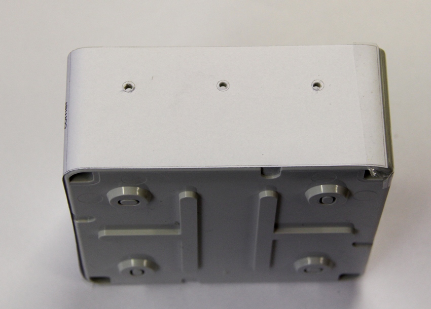
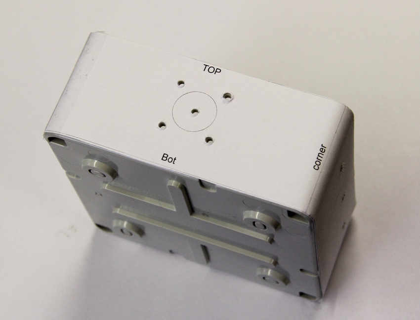
The drill drawing
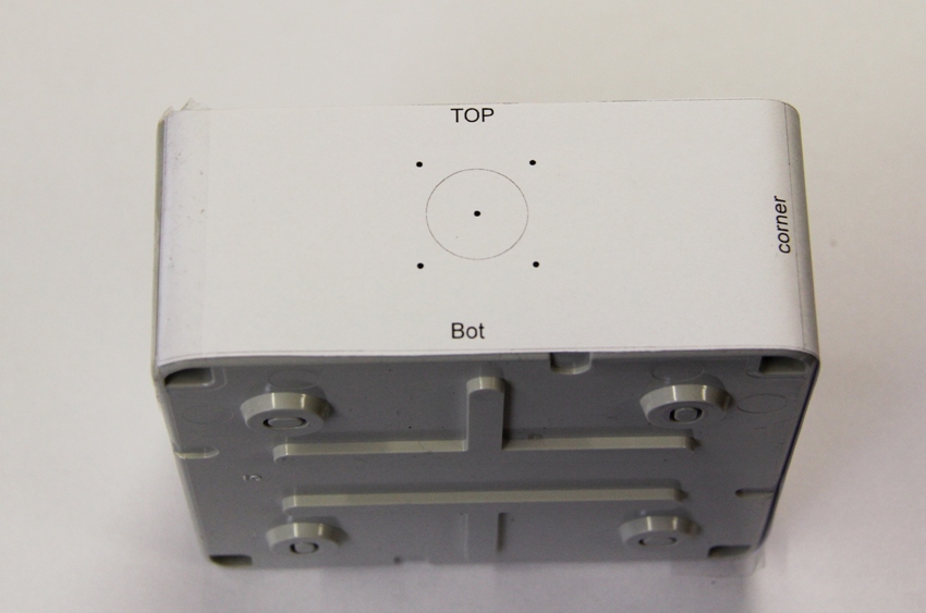
Paste the drawing on the box and fix it with some tape.
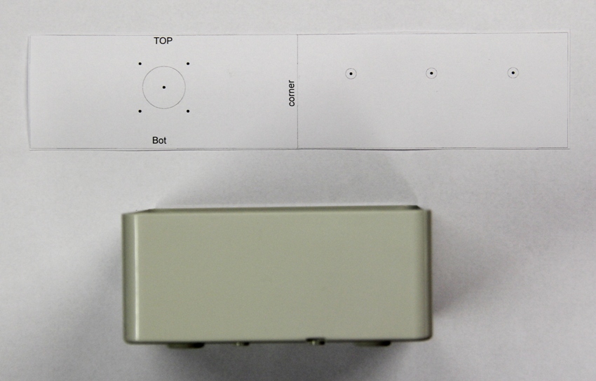
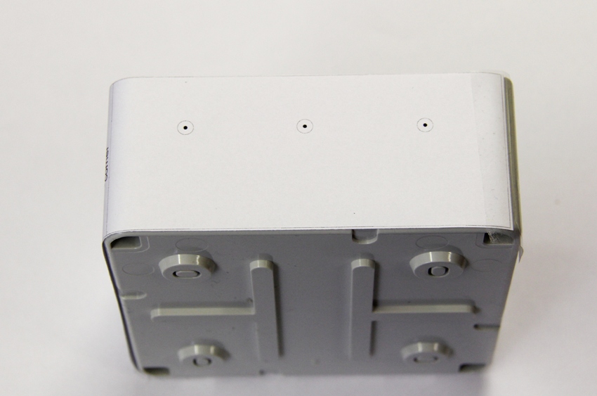
Drill 3 or 3,2mm holes for connector.
Drill 4mm holes for antenna screws.
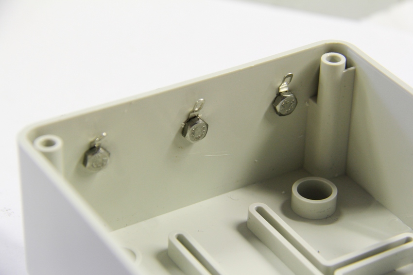
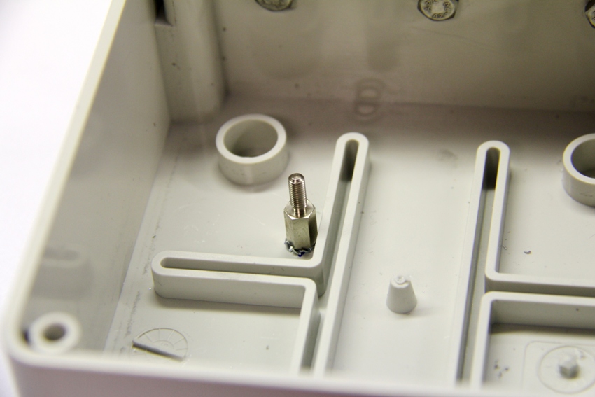
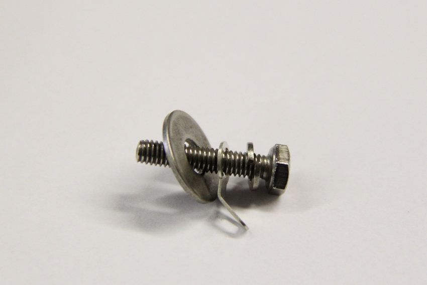
Bend the screw heads into box
- use 6mm drill and do it slowly by hand
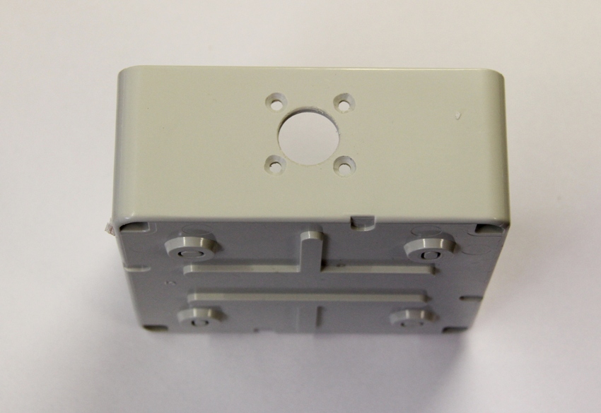
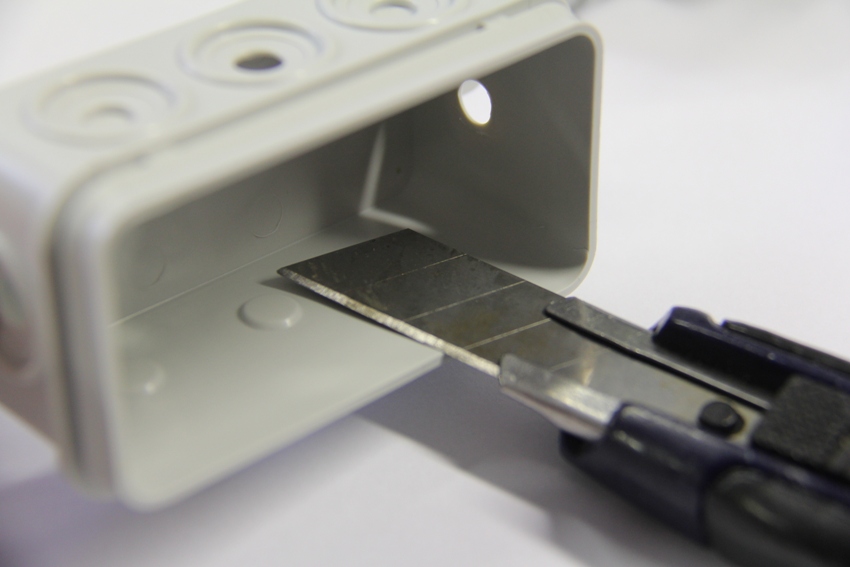
- drill 16mm hole for connector
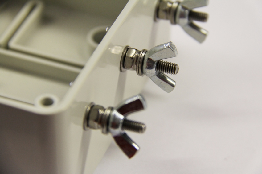
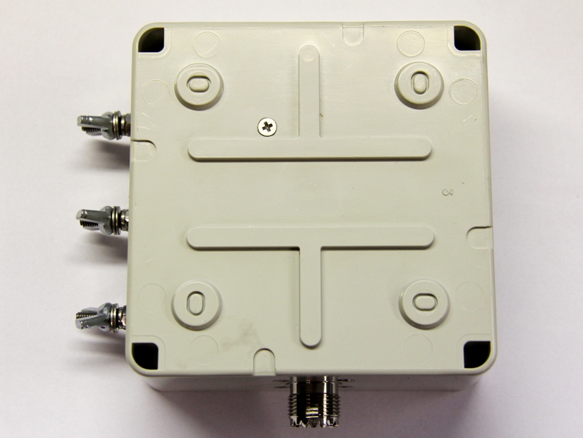
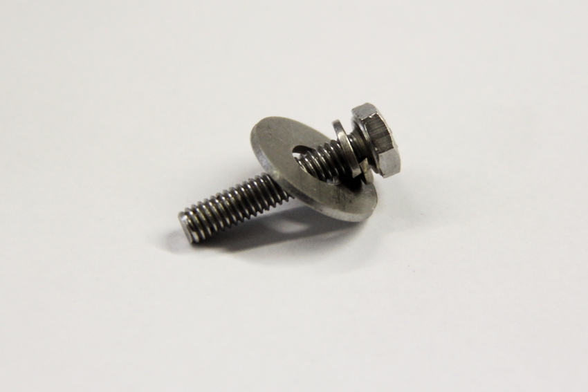
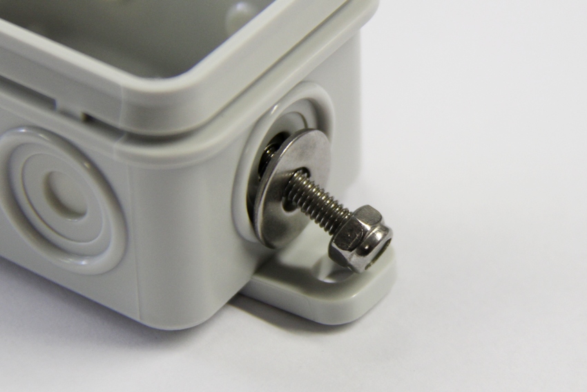
Insert the screws
Insert stainless screws 4mm with
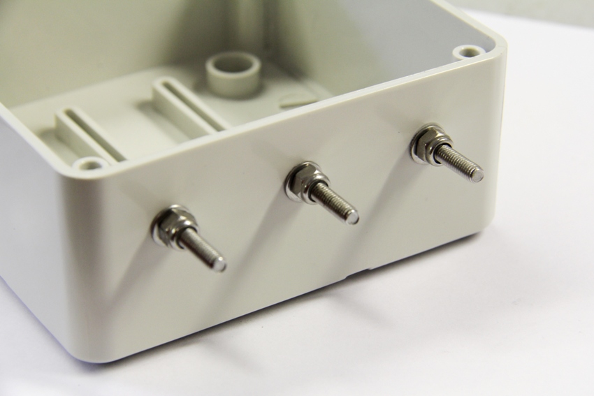
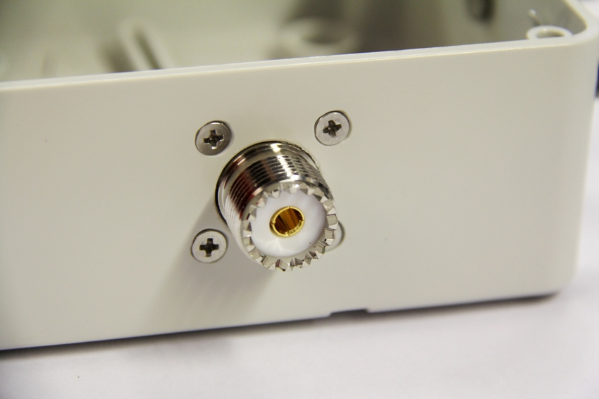
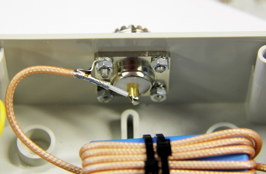
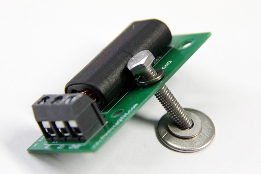
Mount the RF connector
insert connector and use steinless M3x8 and one M3x10 with grounding eye.
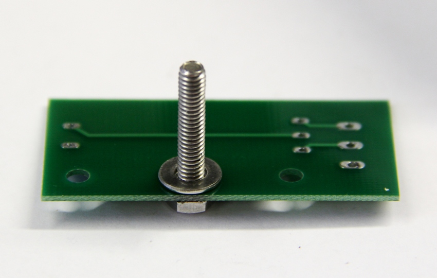
Drill the hole for the PCB holder
- mark the hole center by the PCB
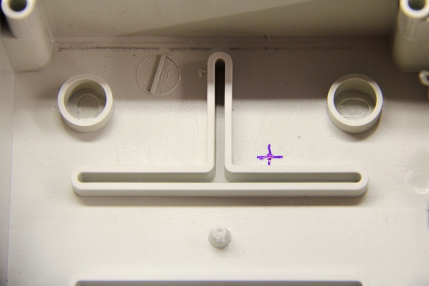
- drill the 3 to 3,2mm hole.
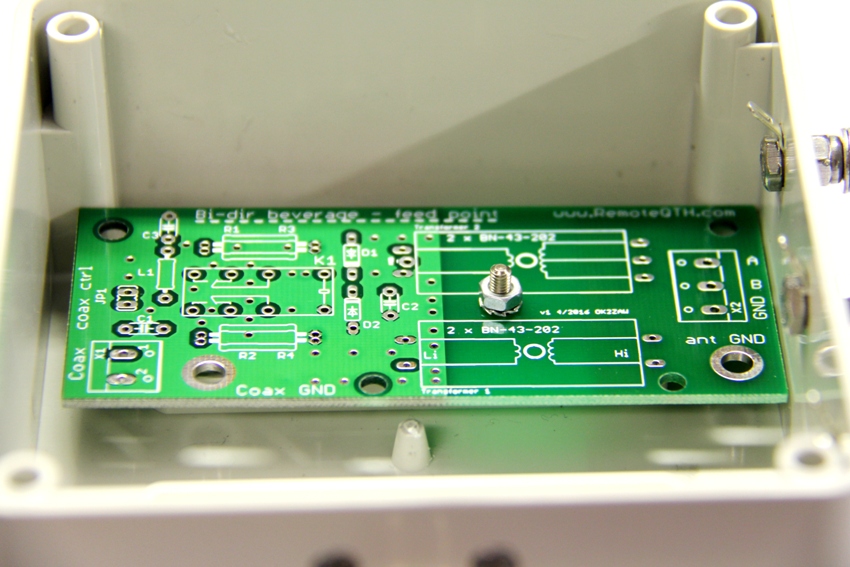
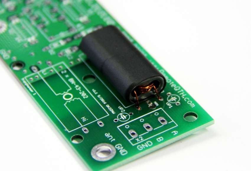
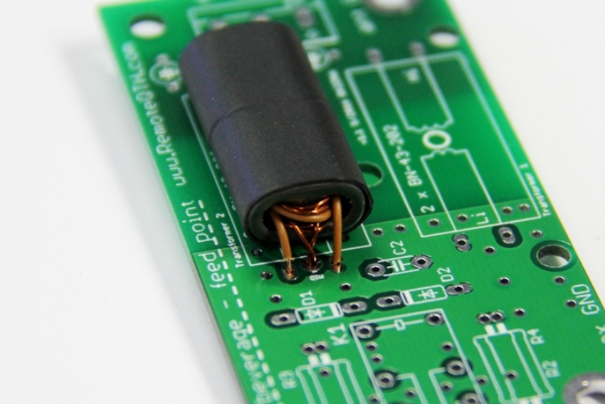
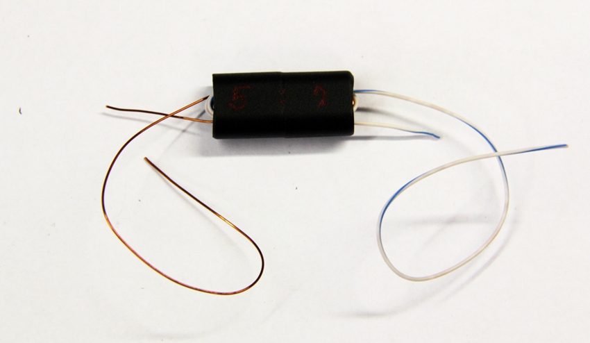
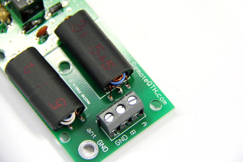
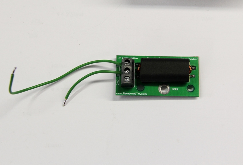
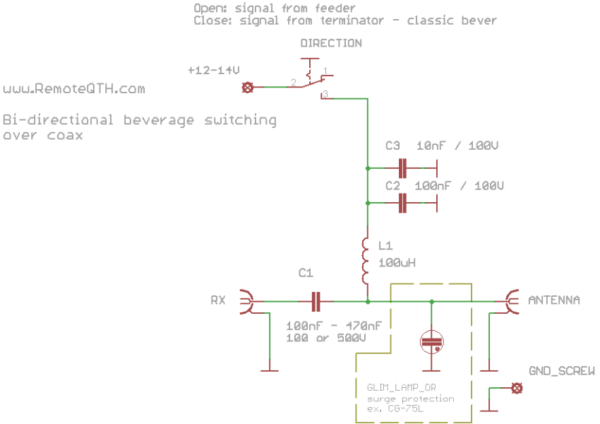
Feeder PCB assembling
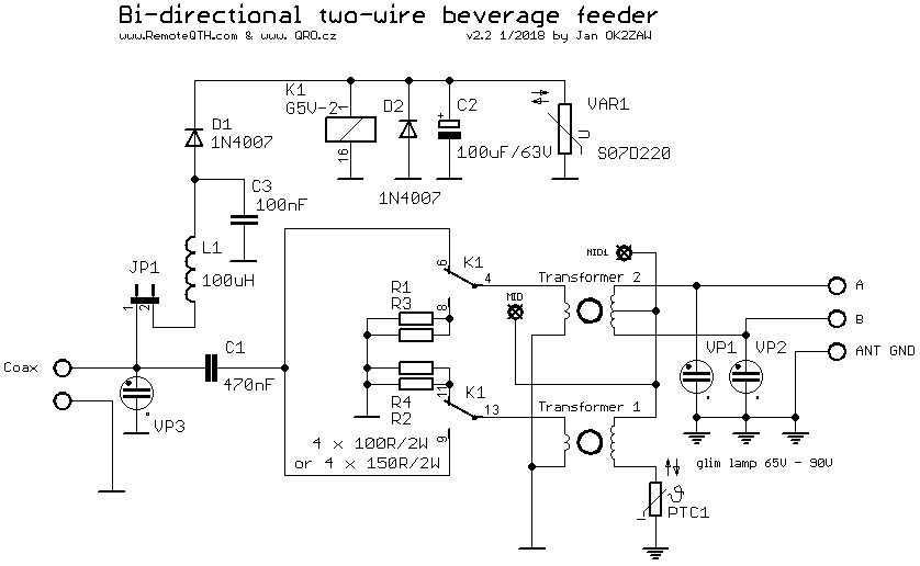
- USE 4 X 100R/2W for 50 Ohm coax feeding OR 4 X 150R/2W for 75 Ohm coax feeding
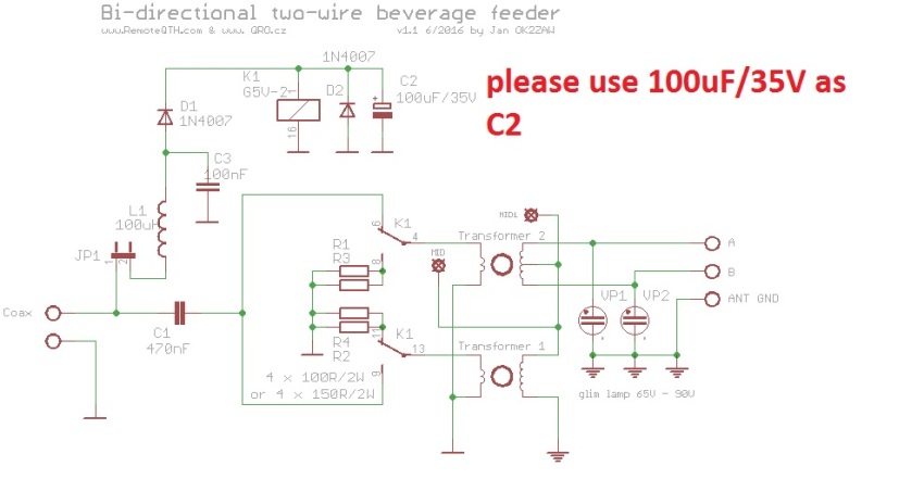
- NOTE !!! PLEASE CHANGE OR ADD 100uF CAPACITOR ON C2
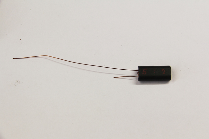
KIT parts example
Assembling
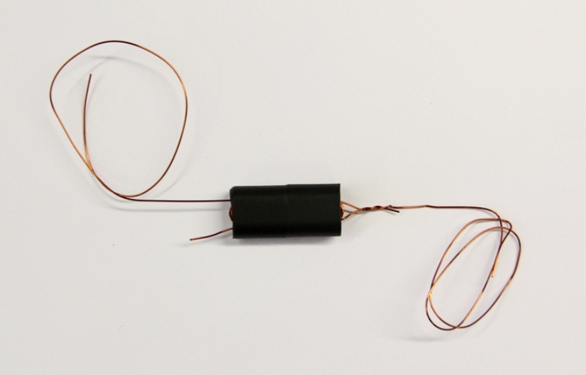
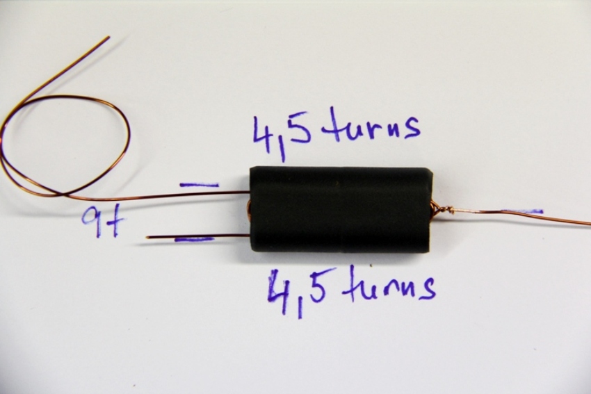
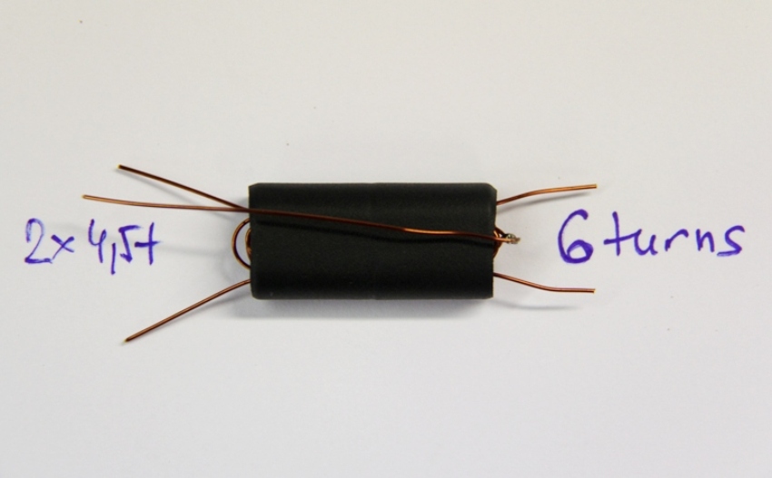
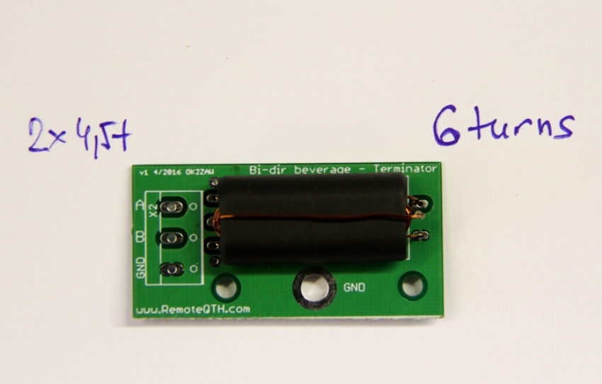
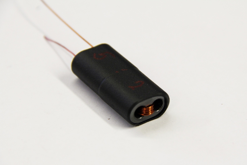
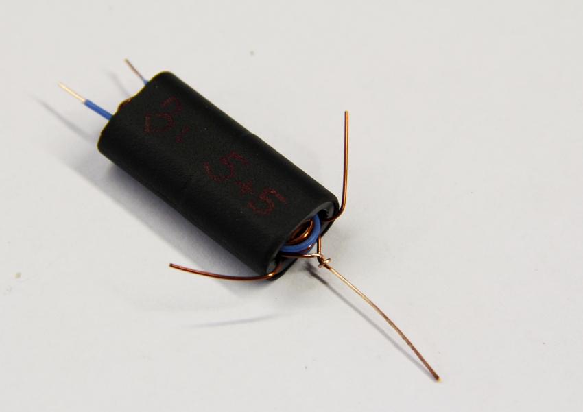
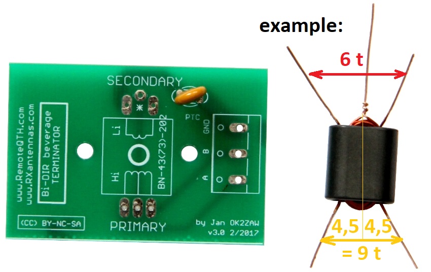
TRANSFORMERS winding - very important thing!
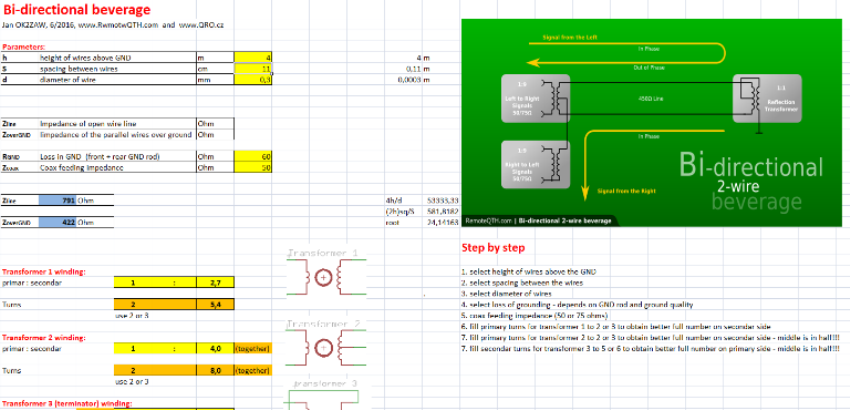
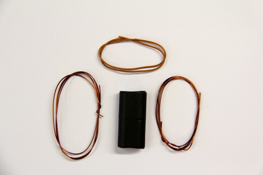
- example of some transformers
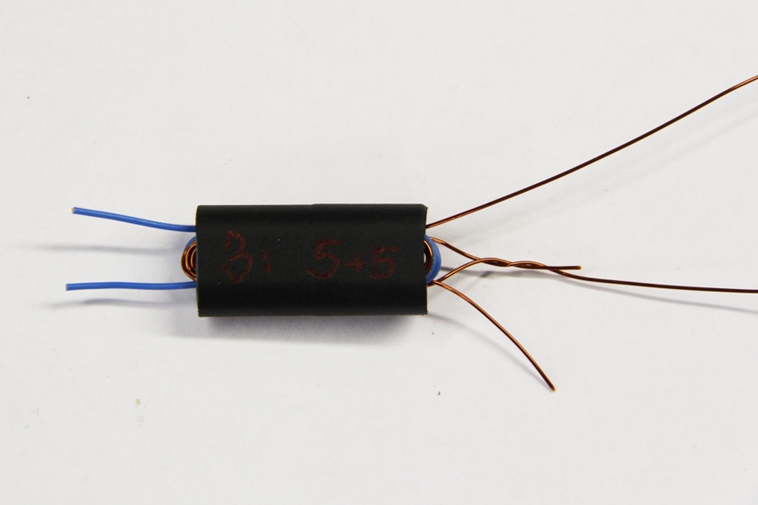
- example of 3,5 turns
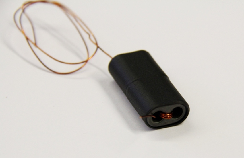
- 2 times 3,5 turns
- 2 x 3,5 turns on secondar and 2 turns on primar
- example for terminator 9 turns and 6 turns, where 9 is two times 4,5 turns
- example two time 5 turns and 3
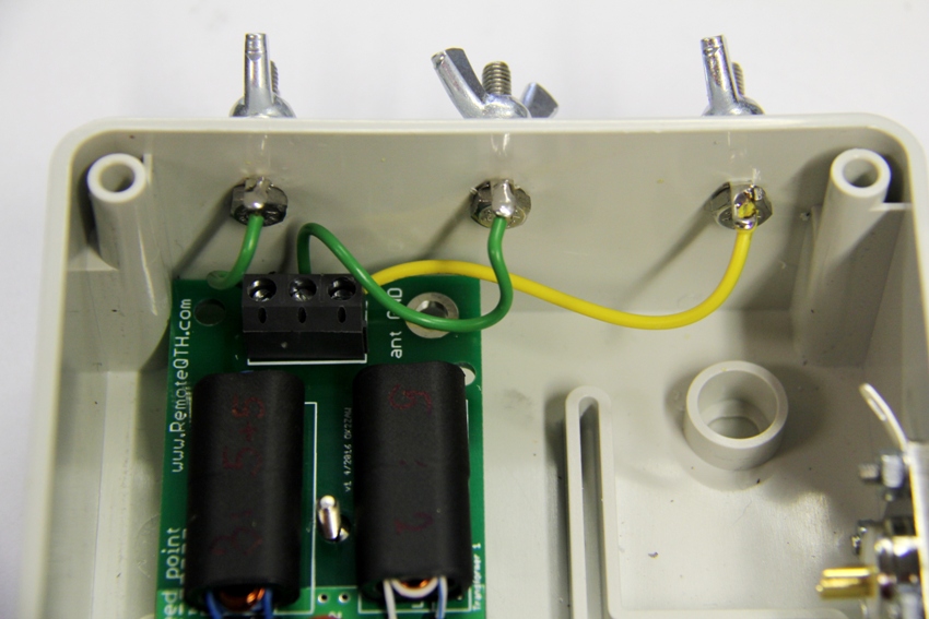
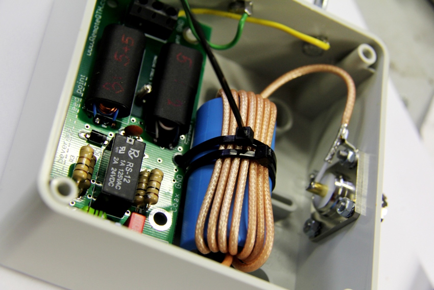
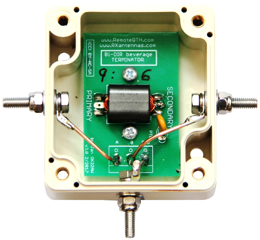
Connect PCB to the screws
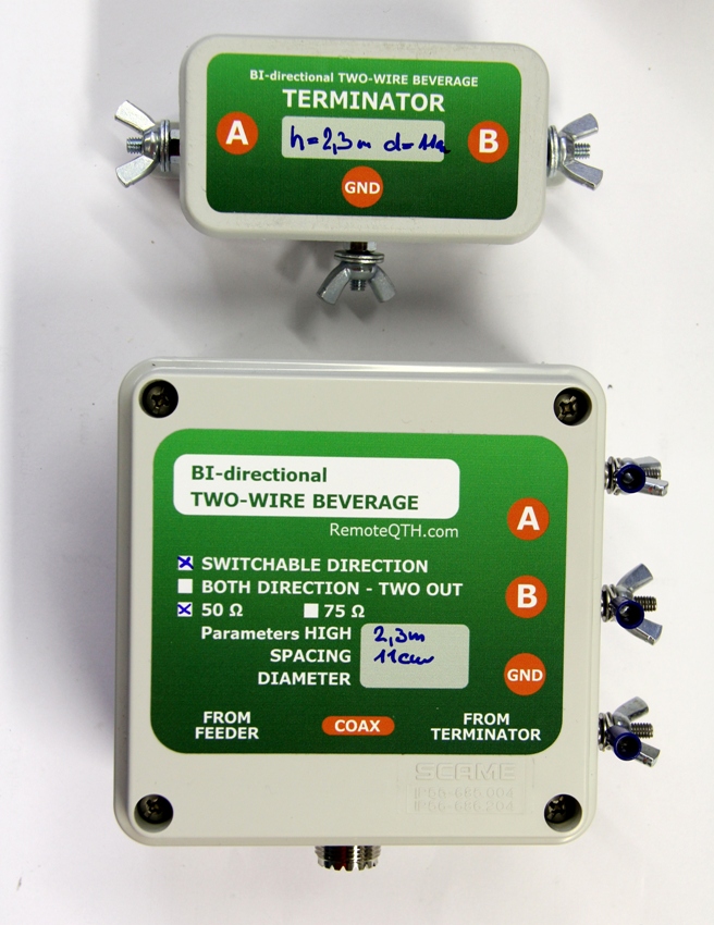
- check the lable on the box and connect wires. There must A, B and GND connected to right screws on the box.
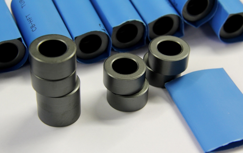
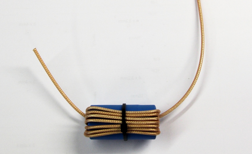
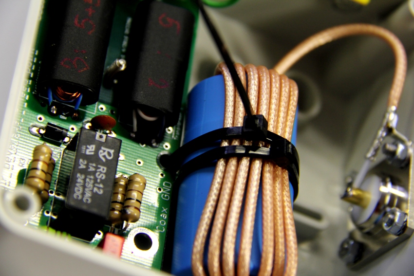
Wind the coax
- Wind the coax as is on the picture, there should be 7 or 8 turns.
- fix it by one binder and use second one to fix choke to the PCB
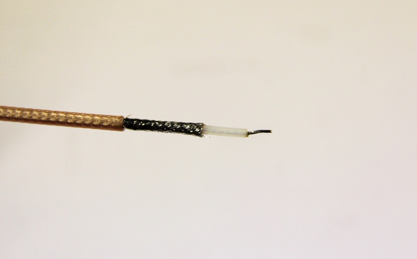
Solder the coax
- use second binder to fix choke to the PCB
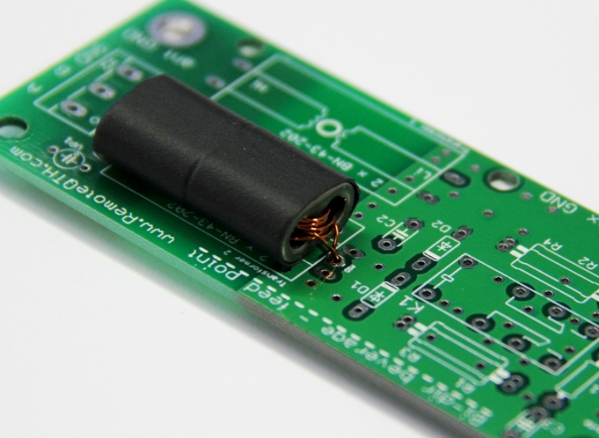
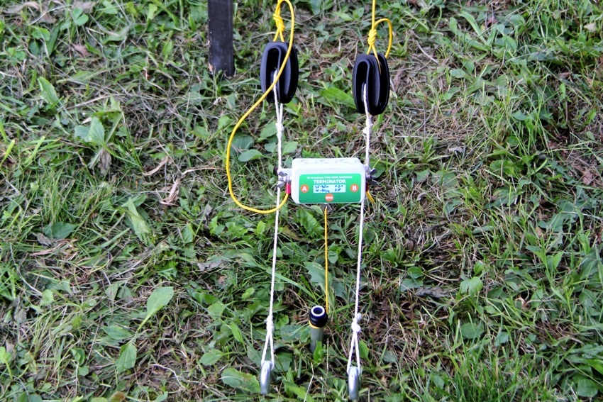
The Terminator
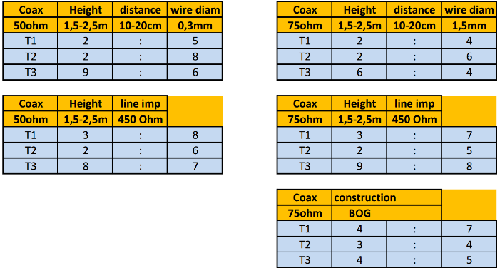
- Do right turns calculation or use table values.
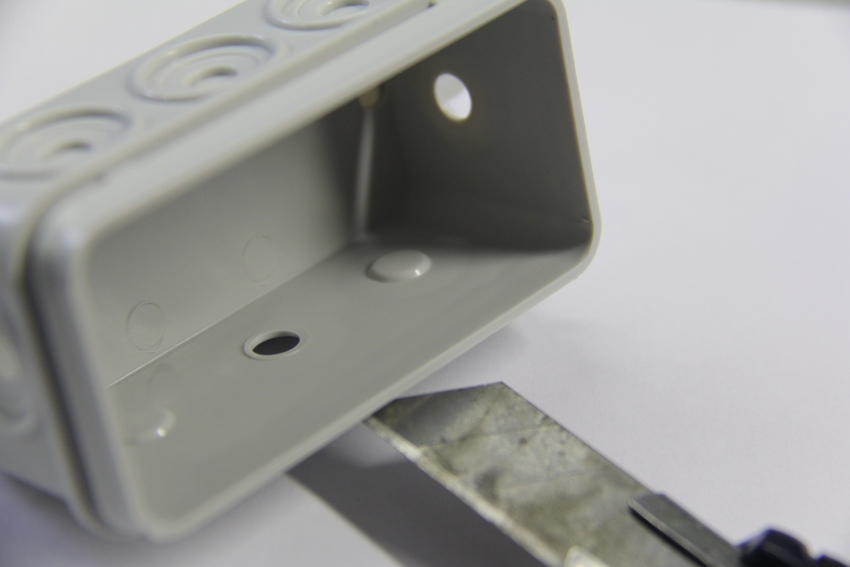
Drill the hole for GND screw
rev.0
rev.1
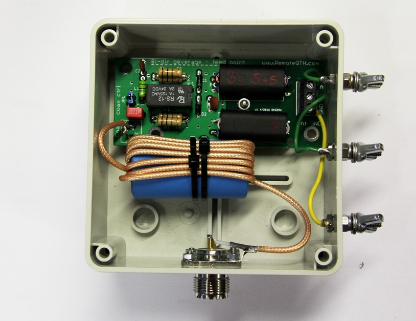
Connect wires
Insert the PCB and fix it with the steinless M4 screw.
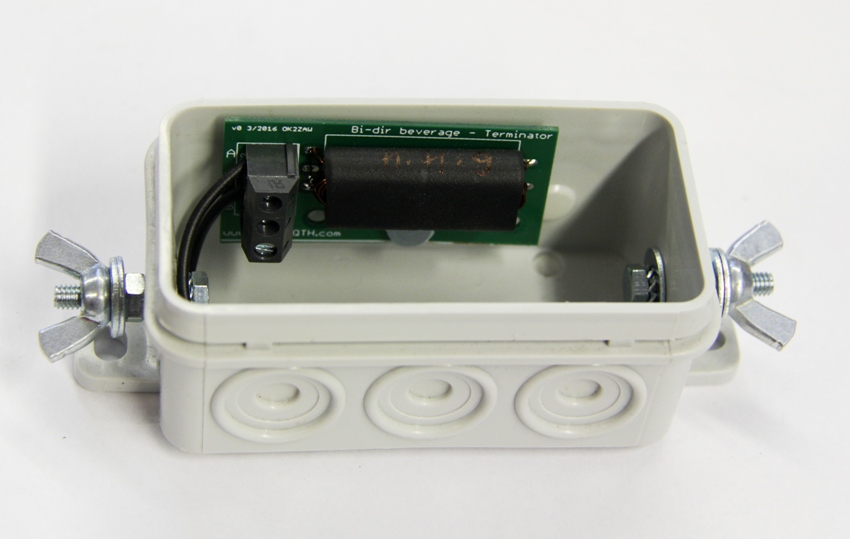
Connect the wires to the screws.
- Connect in the right order! A on PCB to A screw - check the lable on the box
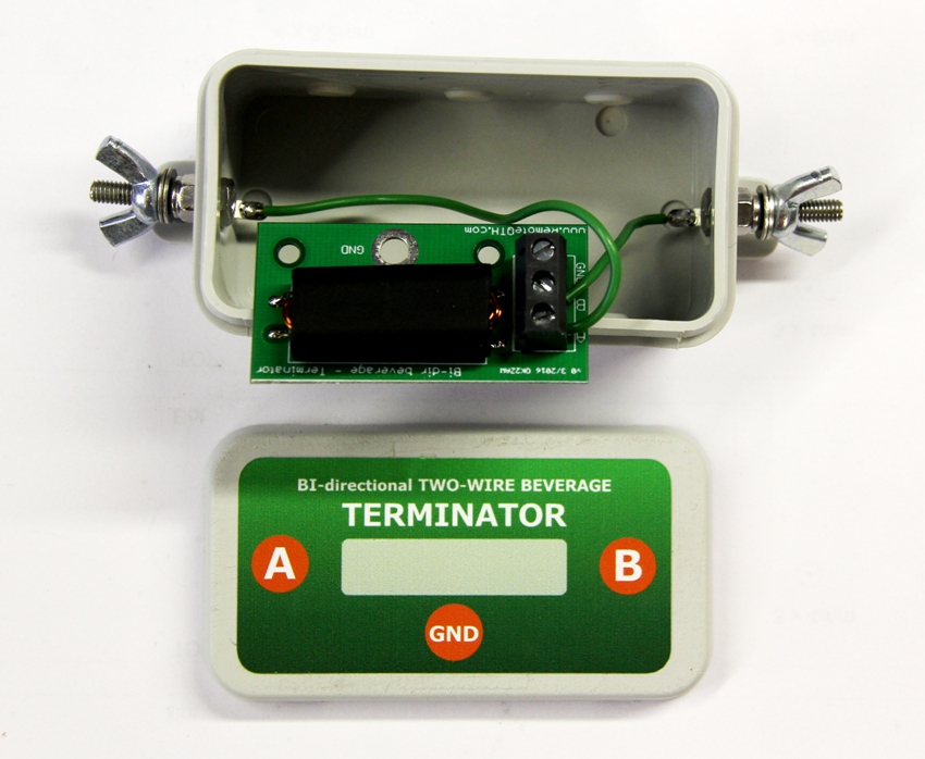
Ready to use. Go to the field! :-)
Example of beverage direction switching
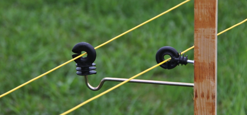
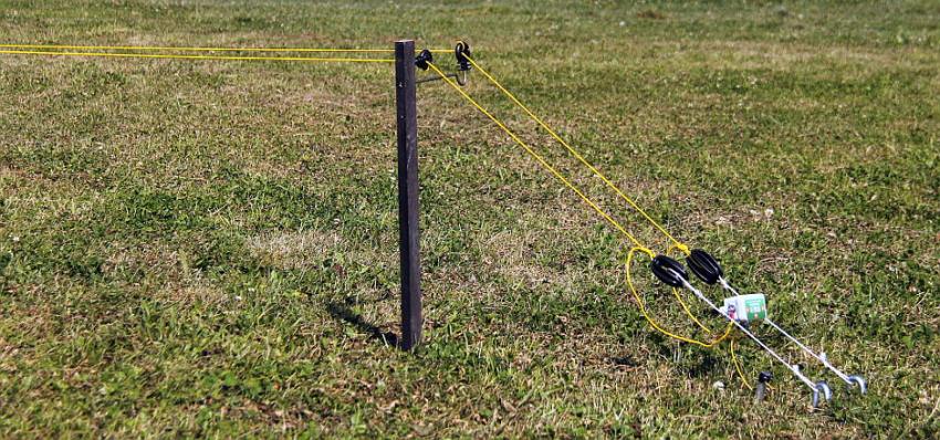
Example of beverage construction
- you can buy it there: Top band beverages and wire antennas acessories
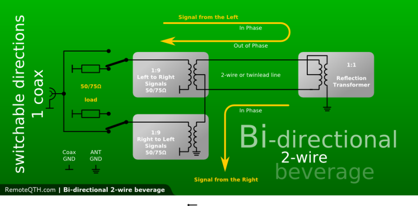
The beverage is a long wire antenna installed very close to the ground. The antenna should be longer than 1 wavelength and installed at a height of less than 0,05 wavelength above ground. The beverage is usually terminated in a resistance at the end (opposite the feedpoint).
Beverage antennas provide one of the least expensive and most reliable ways to improve DX capabilities on the low frequencies.
With careful attention to design and construction, a single beverage antenna can be made to cover two directions with excellent performance over a very wide frequency range.
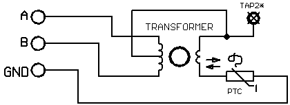
The transformer at the end of the beverage is designed to match impedance of the antenna.
A two-wire bi-directional beverage requires the antenna element to operate a balanced transmission line, as well as a conventional long wire antenna. The parallel wire line used to construct the antenna must be excited under near-perfect balanced transmission line conditions.
This is why each of the parallel transmission line wires must be parallel to the ground. A line should not be constructed in a vertical fashion, using single support poles with one wire under the other. The closer the wire spacing of the line, the lower the impedance of the line, and the less critical installation-related unbalances become. The higher you install the line above ground, the less unbalance any unequal coupling to earth creates.
Source: W8JI, ON4UN
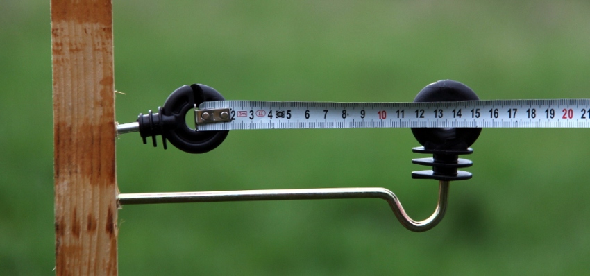
- Example of the construction details. Two wires with the distance of 10 to 13 cm.
External links
- PC5M 4 direction design - source PC5M
- ZL3IX Bi-dir beverage notes