K9AY_VER_1
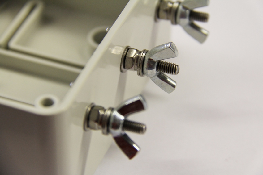
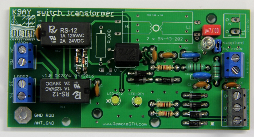
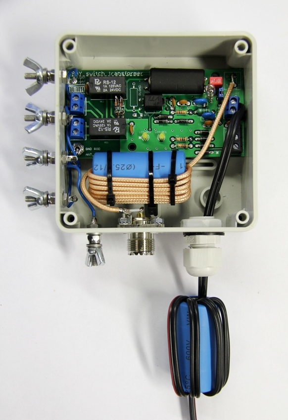
Assembled KIT
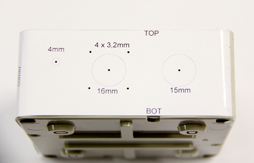
The drill drawing
Paste the drawing on the box and fix it with some tape.
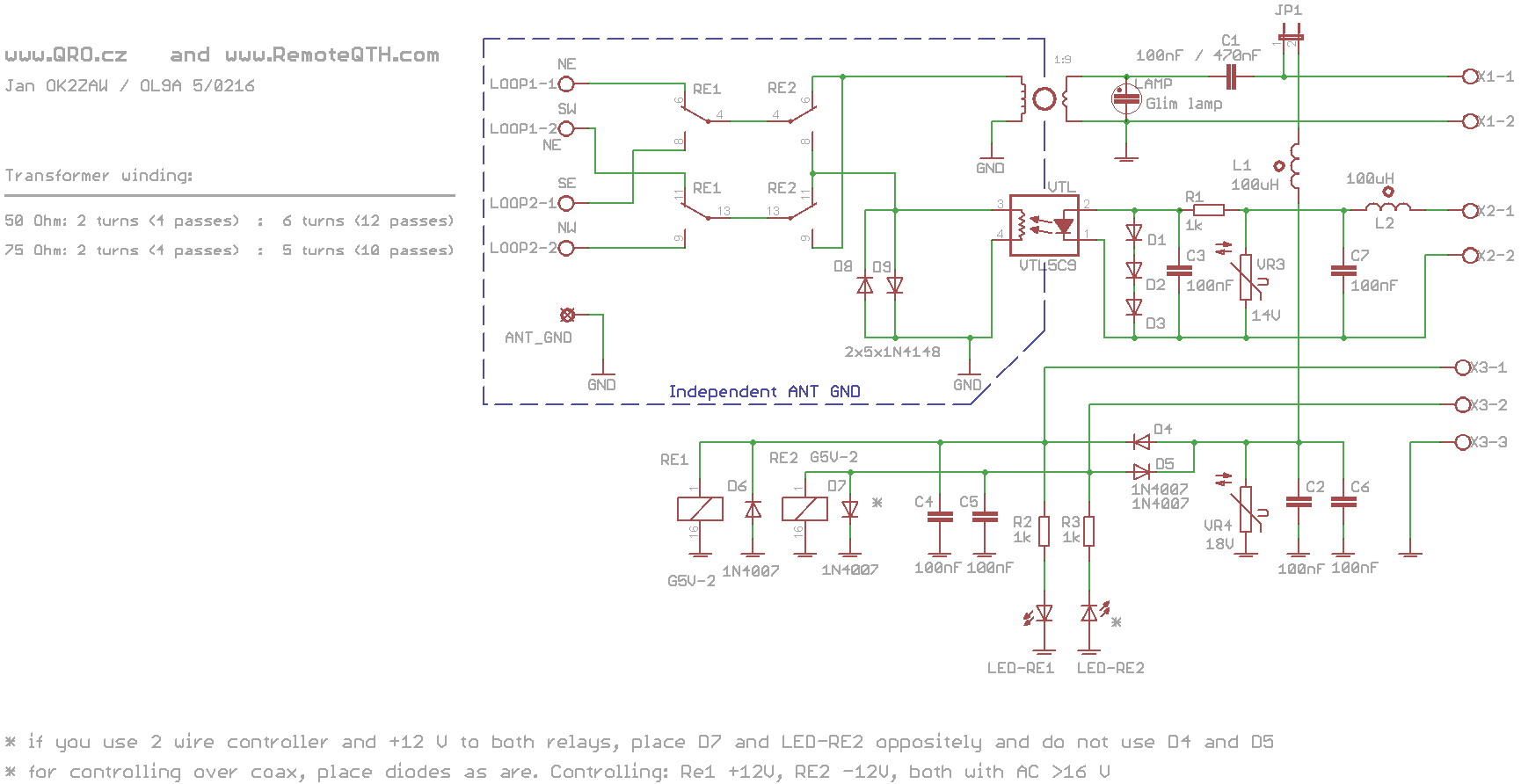
Schematic diagram
- Schematic V < 2.0
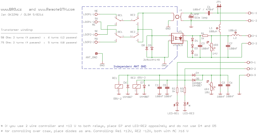
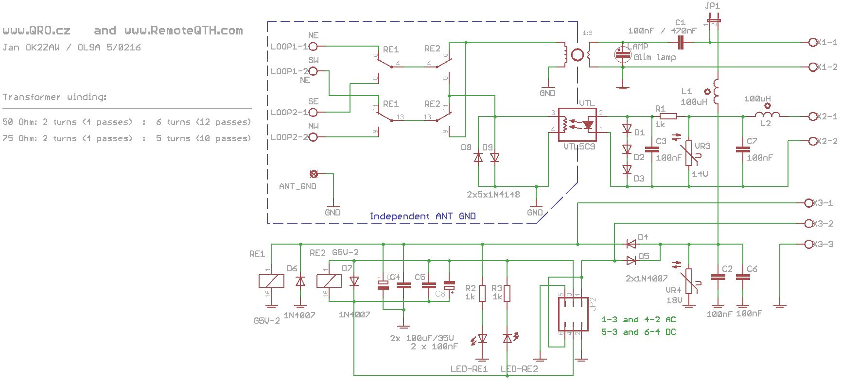
- PLEASE ADD 100uF/35V CAPACITOR OVER C4 AND C5 IN RIGHT POLARITY !!!
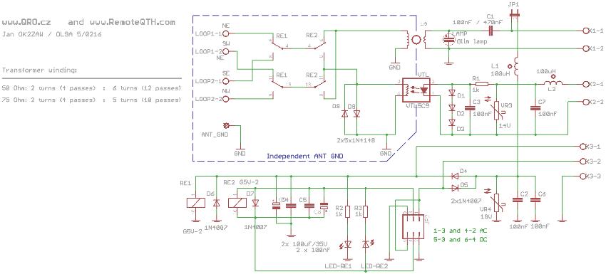
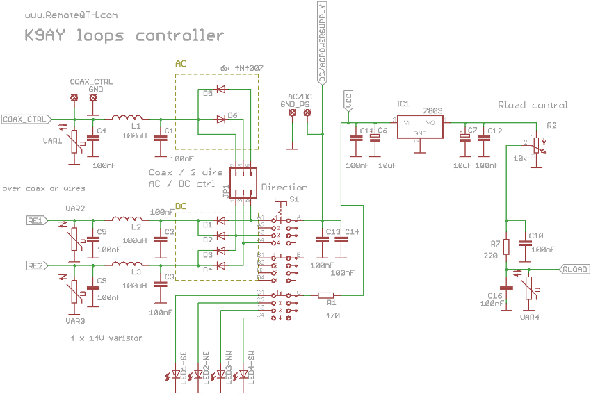
- Schematic Version 2.0

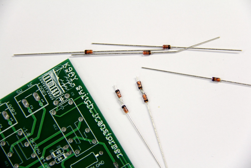
Protection diodes
- solder 5 + 5 diodes
- these diodes protect Rload resistor against high power, electrostatic etc.
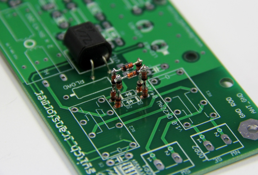
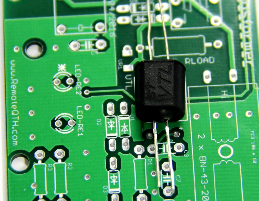
Insert rest parts
- PCB mistake on version 2.0 - sorry for that
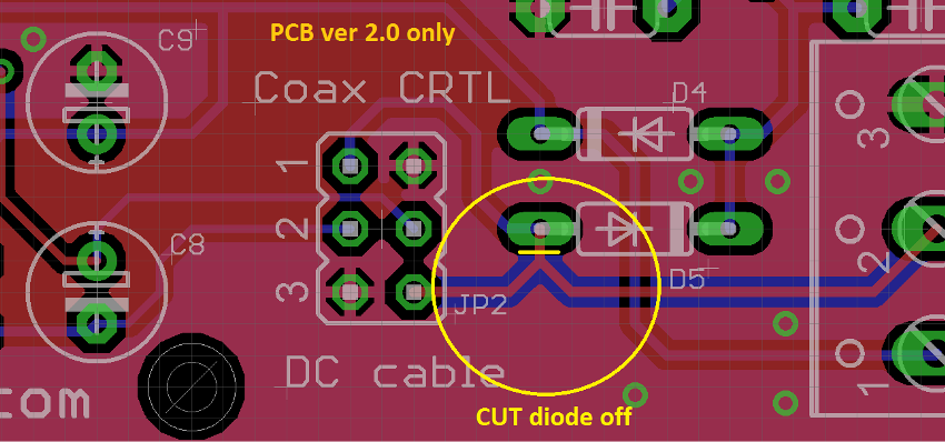
- chooce the control way...
- Version < 2

- Version < 2
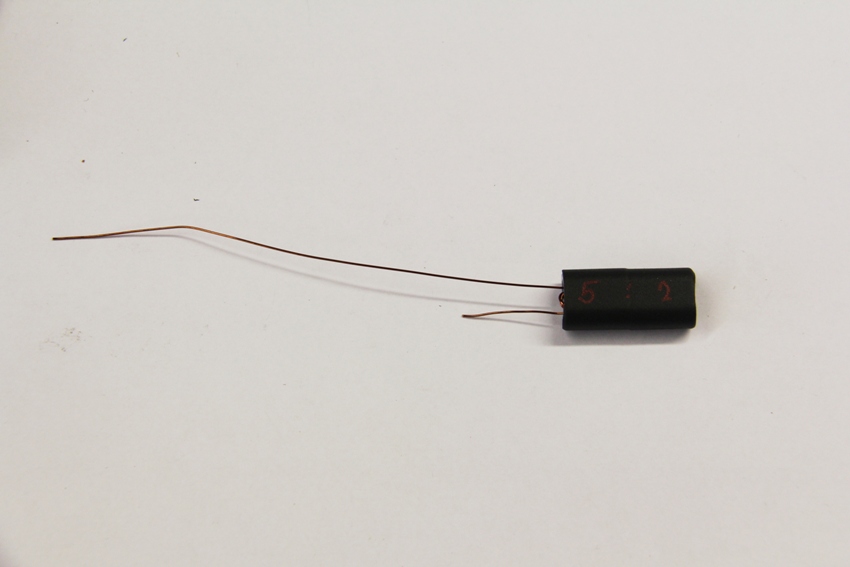
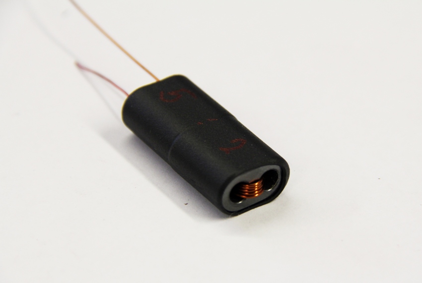
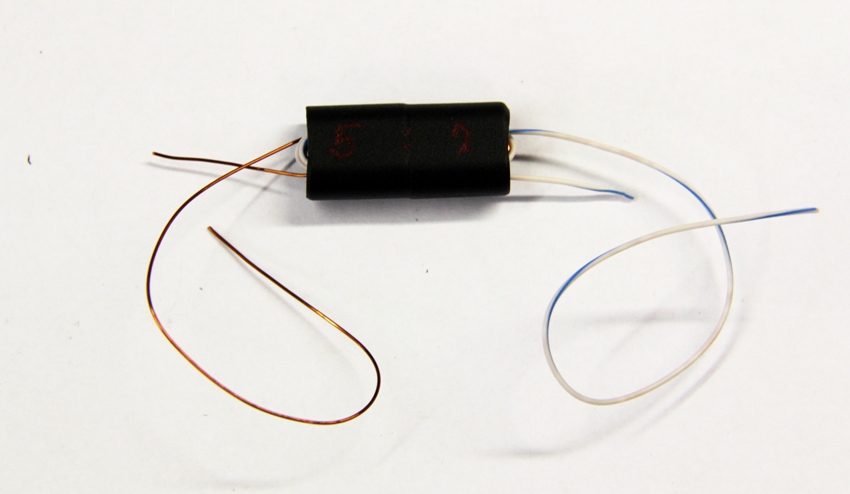
TRANSFORMERS winding - very important thing!
- for 50 ohm coax feed line : 2 turns on primar (coax) and 6 turns on secondar side (loop)
- for 75 ohm coax feed line : 2 turns on primar (coax) and 5 turns on secondar side (loop)
Front side
Front side
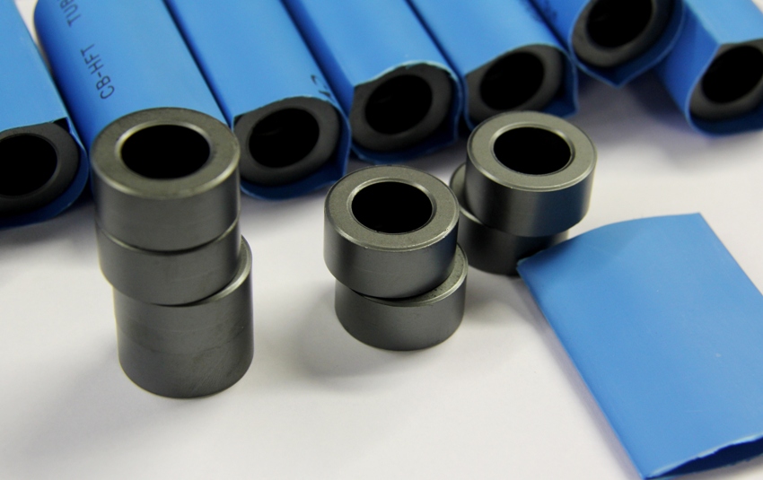
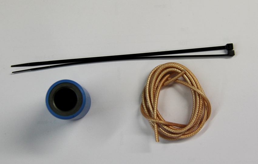
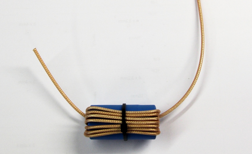
Wind the coax
- Wind the coax as is on the picture, there should be 7 or 8 turns.
- fix it by one binder and use second one to fix choke to the PCB
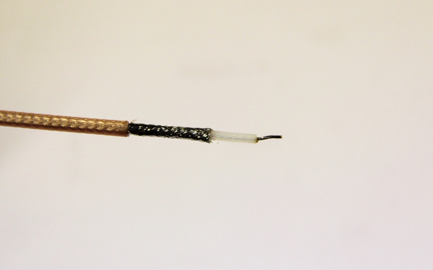
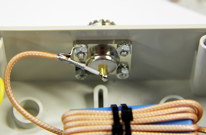
Solder the coax
KIT vertion 1
KIT - all parts assembled.
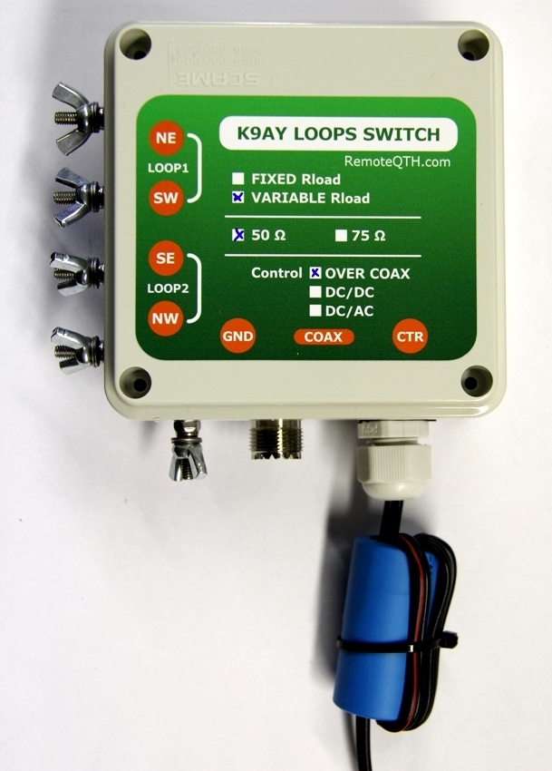
Example of controller.
- Injector to coax line:
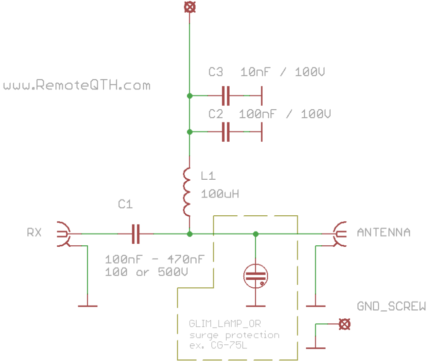
- direction and VAC Rload controller
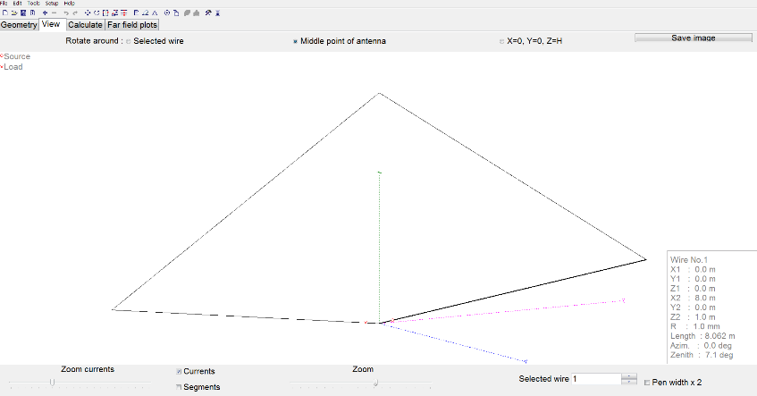
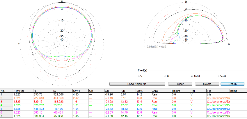
K9AY loops design example.
- It is VERY recomended to place K9AY loop antenna as far as possible from metal towers, antennas and wires. This hepls to obtain better paramaters of antenna ( directivity and noise ).
- MMANA file of my small design for 160 and 80m