Raspberry PI B+ GPIO interface board 2.1
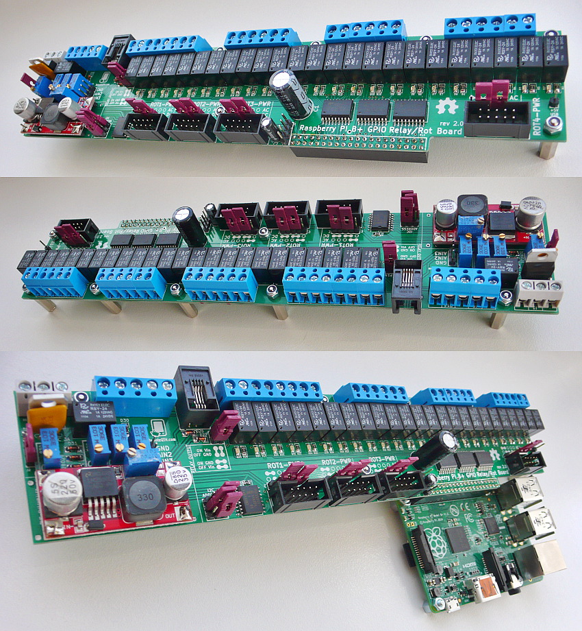
Specifications
- 5V Power supply.
- 24 Relay + LED, controlled from Rapsberry PI B+ GPIO
- Configurable output relays (Vin/GND) in the ON and OFF state seperatly.
- A/D converter with 4 inputs.
- I2C output for connecting the temperature sensor.
- Conector for power and configure four Arduino rotator interface.
- The PCB size 5x25 cm
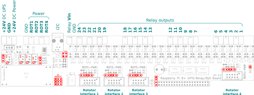
Connectors
- J1 +24V DC Power
- J6 J15 - four rotator interface AC od DC Power
- J5 - RJ9 connector for other I2C temp sensors
- P16 - where the relay switch voltage on outs, here is voltage IN
- P1-P12 - GPIO Relay outputs
- J7-J10 - connect four rotator interface
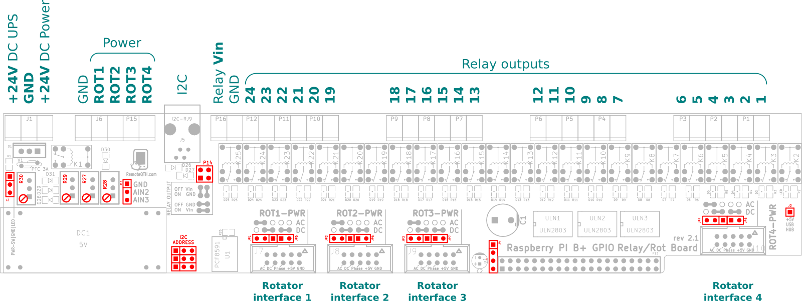
Jumpers
- J2 - Power switch and LED
- J11 - two free A/D inputs
- P4 - preset relay outputs - ON and OFF separately
- I2C - set address A/D converter
- JP1-JP8 - preset power each rotator interface separately
- J4 - I2C bus
- J3 - switched +5V for USB hub