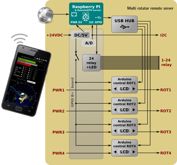
Remote multi rotator control
This revision is from 2014/08/20 14:57. You can Restore it.

- Block diagram
- Rack case
- Rotators module
- GPIO board for model B2+
- GPIO board for model B
- How to assemble components to complete server
- software Configuration
Block diagram

Rotators module
software Configuration
- configure Arduino firmware by K3NG
- download stable or unstable and doc
- custom pins.h
- Enable LCD Display -> (by delete // at the three lines.)
#define FEATURE_LCD_DISPLAY
#include <LiquidCrystal.h>
LiquidCrystal lcd(lcd_4_bit_rs_pin, lcd_4_bit_enable_pin, lcd_4_bit_d4_pin, lcd_4_bit_d5_pin, lcd_4_bit_d6_pin, lcd_4_bit_d7_pin);
- Change the Baud rate to 9600 (at K3NG source code its 115.k baud the preset)
#define SERIAL_BAUD_RATE 9600
- install RemoteQTH server on SD card for Raspberry PI
- login (yourcall/1234)to web interface and update server from status page
- change login and password in menu SETTINGS/LOGIN
- in menu SETTINGS/WEB RELAY change name for first relay to POWER and others set to n/a
- in menu SETTINGS/ROTATORS set number on Four and configure each rotator
- set Name
- replug usb and find ID from pop-up window
- From/To azimuth without overlap
- Get/Set sommand by defaukt
- Your locator and apply
- For detection USB interface replug all interface by turning power off from the menu CONTROL/SWITCH RELAY - Recognized USB devices shown in STATUS page as rot1 , rot2, rot3 and rot4


