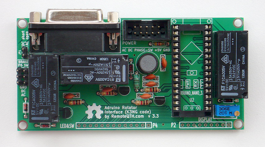
Rotator module version 3.3
This revision is from 2015/11/12 20:37. You can Restore it.
- Power
- Connect DC Rotator (DB15 female) and power inputs
- Connect AC Rotator (DB15 female) and power inputs
- Use with original control box
- Two wire azimuth potentiometer hardware addon from DM2RM
- Ten turn azimuth potentiometer bridge
- Control software
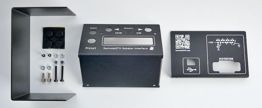
Components of Multi rotator controller server
Planting plan
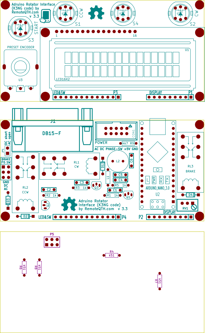
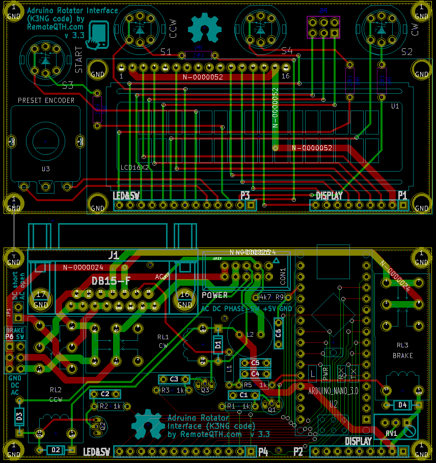
Part list
| Main and LCD PCB | two PCB |
| C1,C2,C3,C4,C5, C6 | capacitor 4n7 |
| D1,D2,D3,D4 | diode 1n4148 |
| L1 | inductor 150uH |
| L2 | inductor 220uH |
| R1,R2,R3,R5 | resistor 1k |
| R9 | resistor 4k7 |
| R4,R6,R7,R8 | resistor 510R |
| RV1 | potenciometer 1k |
| Q1,Q2,Q3 | transistor BC547 |
| S1,S2,S3 | LED switch |
| RL1,RL2,RL3 | Relay |
| U1 | LCD 16X2 |
| U3 | preset encoder with knob |
| J1 | DB15-F + DB15-M |
| CON1 | pin array 5x2 |
| P2+P1, P3+P4 | strip 9+13 pins 90° |
| P5 | pin array_3x2 |
| P6, JP1 | pins + jumper |
| U2 | Arduino nano 3.0 + socket |
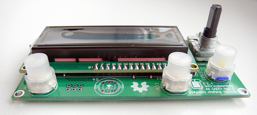
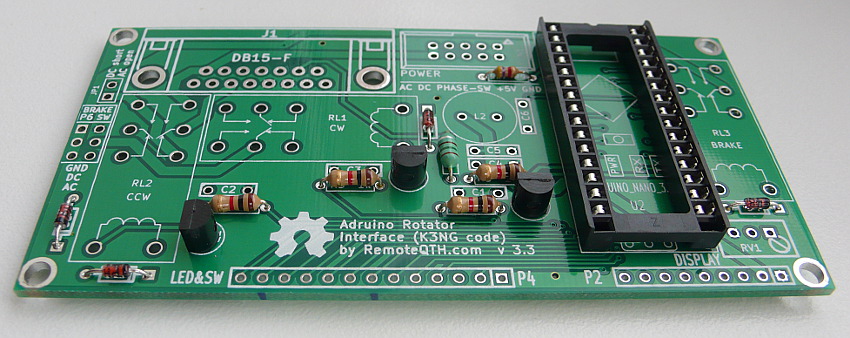
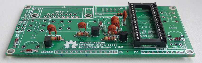
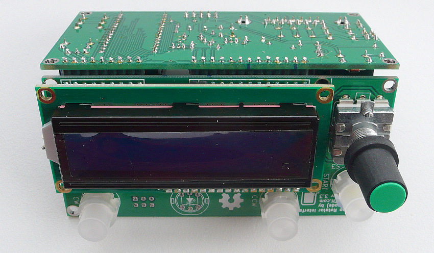
Assembly gallery
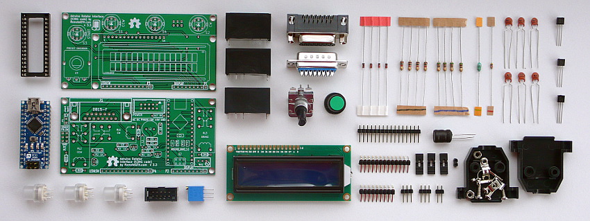
✔ All components
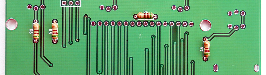
❏ Solder R4 R6 R7 R8 (marked in blue)
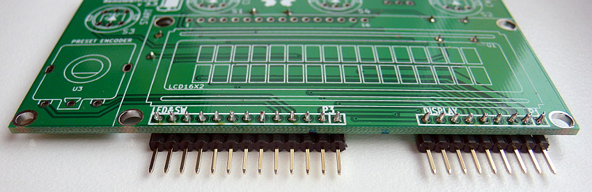
❏ 13 and 9 pins 90° strip
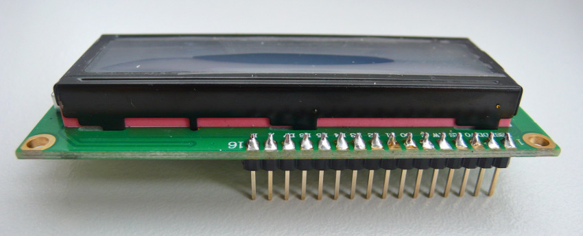
❏ 16 pins strip to LCD
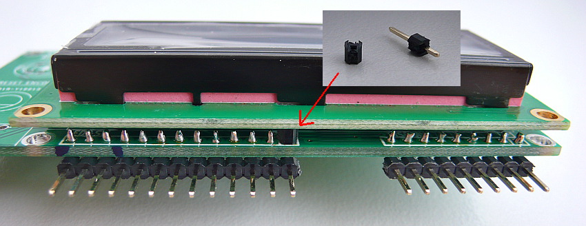
❏ Insulating spacer washers between LCD and PCB
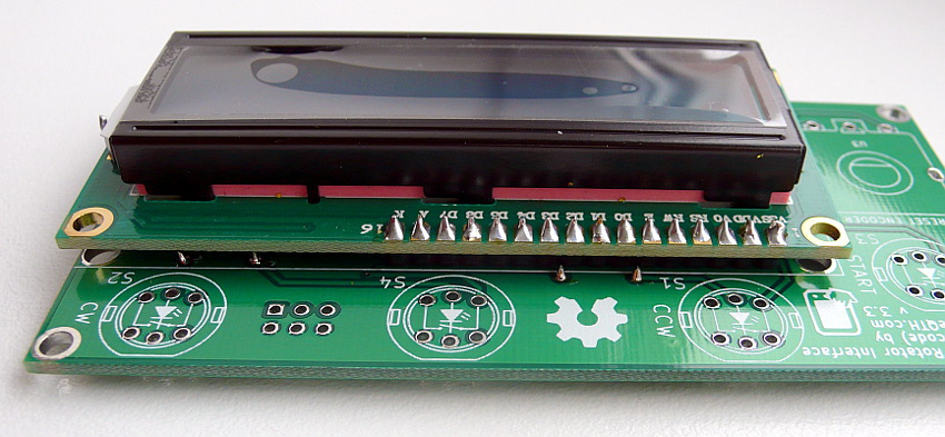
❏ LCD module to PCB
❏ CW, CCW and START switch (marked in blue) and preset encoder, Now front panel is final
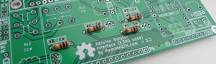
❏ Next R1 R2 R3 R5 (marked in black) and R9 solder on main board
❏ D1 D2 D3 D4 (marked in red)
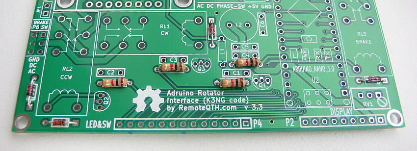
❏ L1 (marked in green) R9 (marked in red)
❏ Q1 Q2 Q3 and Arduino socket
❏ C1 C2 C3 C4 C5 and C6
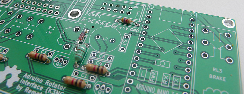
❏ JP1 P6 CON1
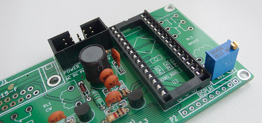
❏ L2 RV1
❏ RL1 RL2 RL3 J1
❏ solder front panel via pin strip
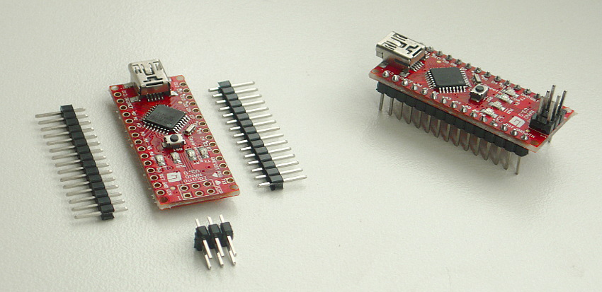
❏ Last solder Arduino Nano pins
❏ Plug Arduino Nano to socket U2
❏ after power up, preset LCD contrast with potentiometer RV1
Firmware
For beginners Getting Started with Arduino
You can configure firmware from master tree Arduino firmware by K3NG
Or download preconfigured version
Please read author documentation
Power
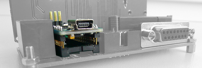
The entire module can be powered from USB only, but there is a voltage drop, it is better to use an external +5V source, or a DC/DC converter and cut the power to the attached USB cable.
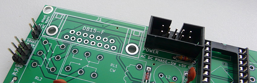
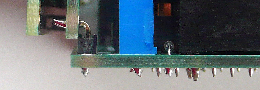
Pin 3 in CON1 (+5 volts input to supply measure the azimuth)- input stabilized voltage from power board This pin may be short connected (as picture below) with pin4 CON1 (+5 volts to interface), then the voltage measurement uses a common 5V voltage from the power supply module.
Connect DC Rotator (DB15 female) and power inputs

- Need three jumper
- short DC position P6 jumper switch
- short JP1 jumper
- short PHASE-SW (center) position CON1
- connect example
- Yaesu G800
pin DB15      G800 unit
-------------------------
     1+2  ->  5
     3+4  ->  4
      15  ->  1
      14  ->  2
     GND  ->  3
Connect AC Rotator (DB15 female) and power inputs
Diagram for the common AC and +5V ground
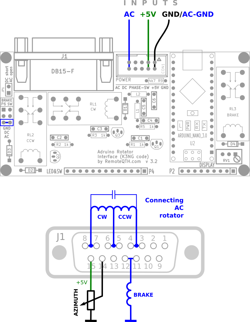
- Need one jumper
- short AC position P6 jumper switch
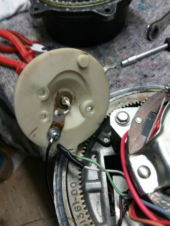
Inspiration potentiometer with grounded center
- Resolving without compromise - the solution is mechanically remove grounded center and connect by three wire
- hardware addon.
- Add resistor with grounded two wire potentiometer - this solutions produce nonlinearity voltage. You can use calibration table
- Circuits
Diagram for the different AC and +5V ground

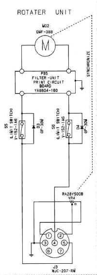
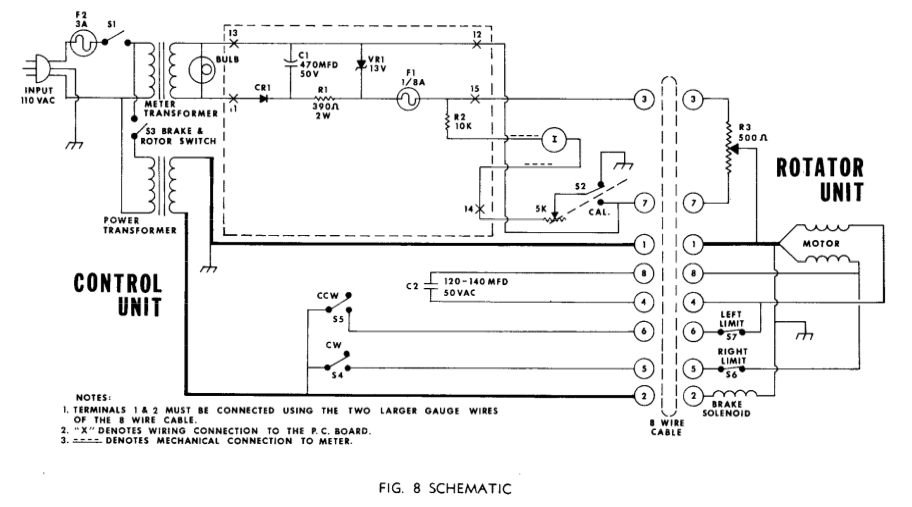
Use with original control box
Two wire azimuth potentiometer hardware addon from DM2RM
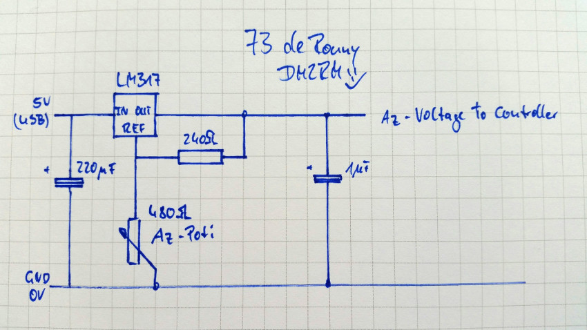
- LM317 rezistor online calculator
- Accurate measurement can be achieved by reducing voltage AREF input to the maximum value of the azimuth potentiometer.
Ten turn azimuth potentiometer bridge
- need negative and positive voltage source
- presset potentiometer bridge to 0 to +5V output
Control software
- PstRotator for Windows
- RemoteQTH server image for Raspberry PI - web interface
- Even software supporting Yaesu GS-232 protocol...