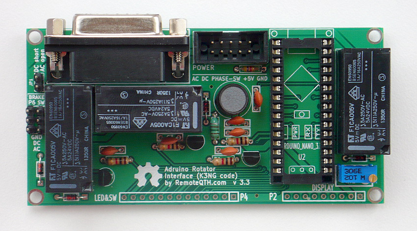
Rotator module version 3.3
- Power
- Connect DC Rotator (DB15 female) and power inputs
- Connect AC Rotator (DB15 female) and power inputs
- Connection examples
- Control software
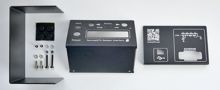
Components of Multi rotator controller server

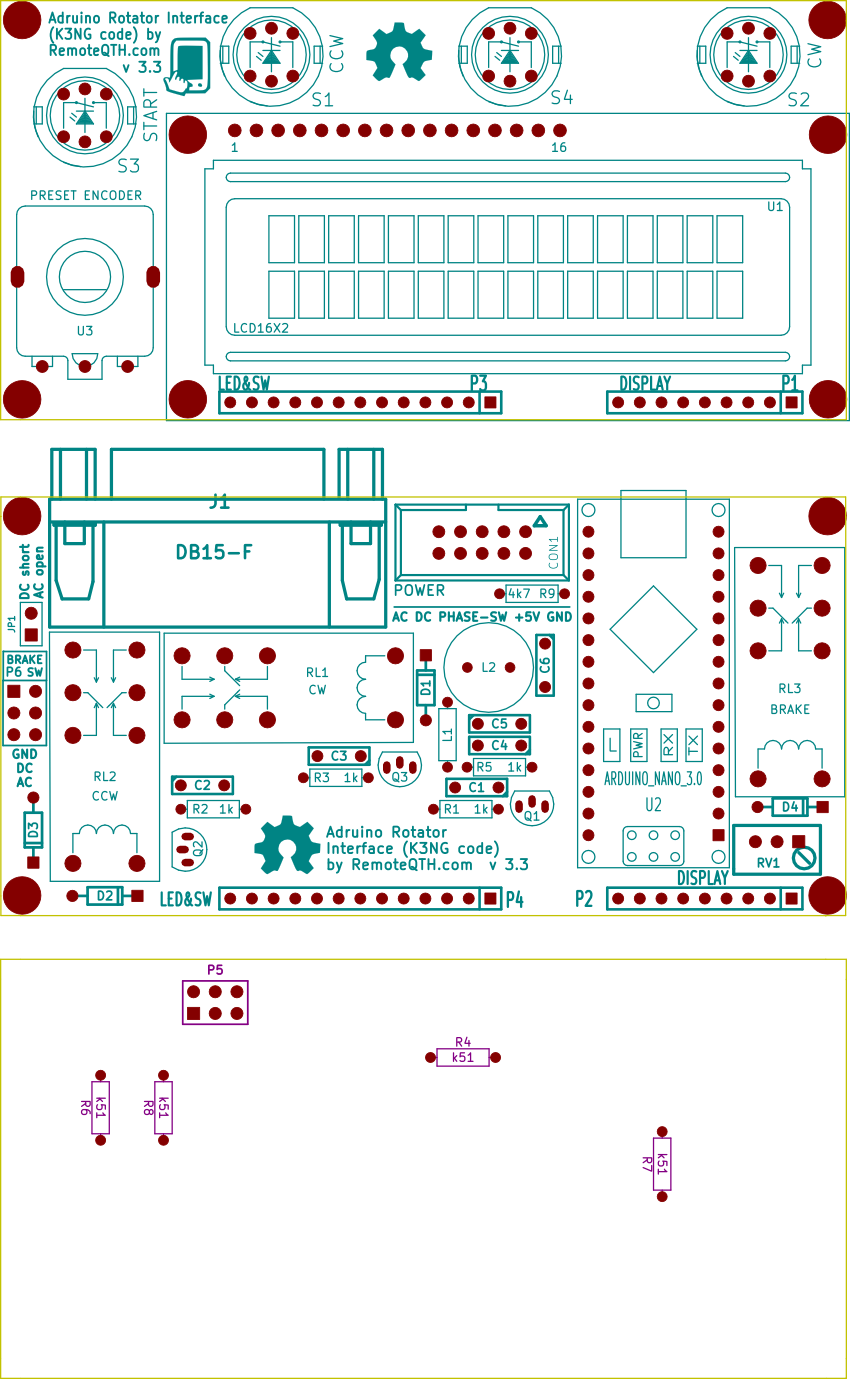
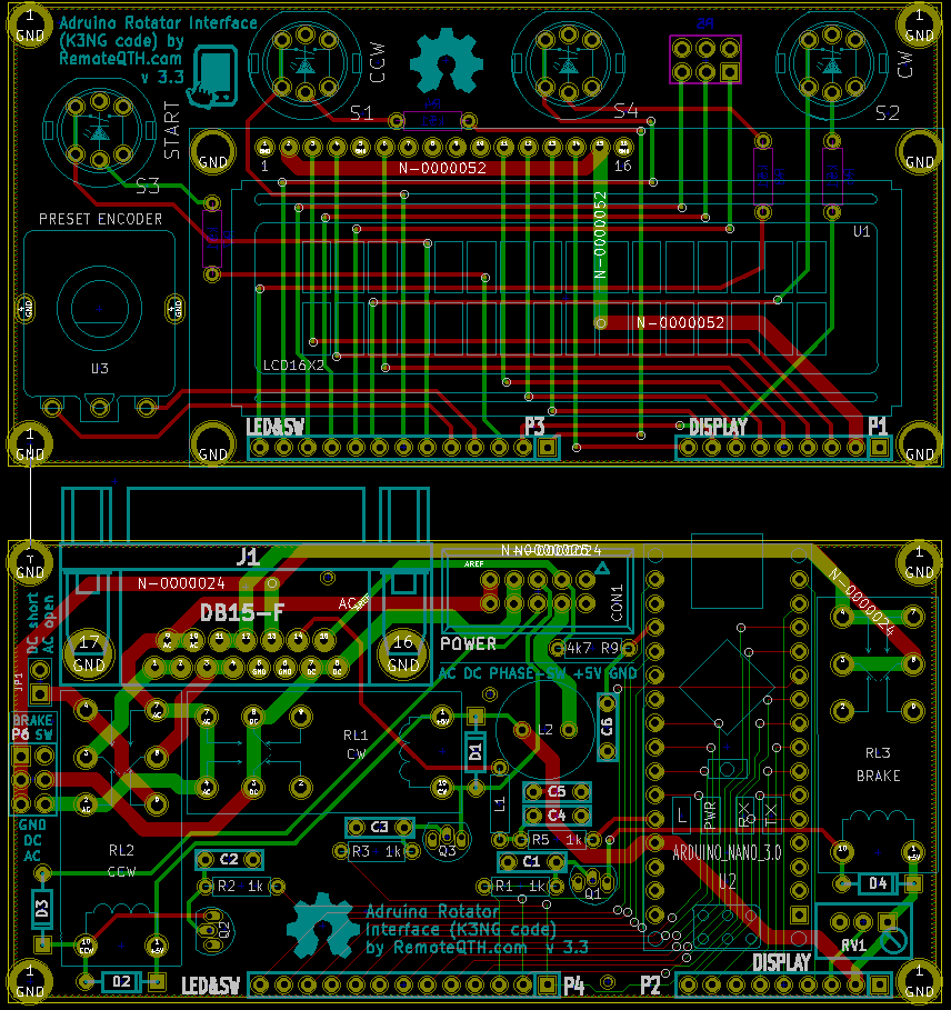
Part list
| Main and LCD PCB | two PCB |
| C1,C2,C3,C4,C5, C6 | capacitor 4n7 |
| D1,D2,D3,D4 | diode 1n4148 |
| L1 | inductor 150uH |
| L2 | inductor 220uH |
| R1,R2,R3,R5 | resistor 1k |
| R9 | resistor 4k7 |
| R4,R6,R7,R8 | resistor 510R |
| RV1 | potenciometer 1k |
| Q1,Q2,Q3 | transistor BC547 |
| S1,S2,S3 | LED switch |
| RL1,RL2,RL3 | Relay |
| U1 | LCD 16X2 |
| U3 | preset encoder with knob |
| J1 | DB15-F + DB15-M |
| CON1 | pin array 5x2 |
| P2+P1, P3+P4 | strip 9+13 pins 90° |
| P5 | pin array_3x2 |
| P6, JP1 | pins + jumper |
| U2 | Arduino nano 3.0 + socket |
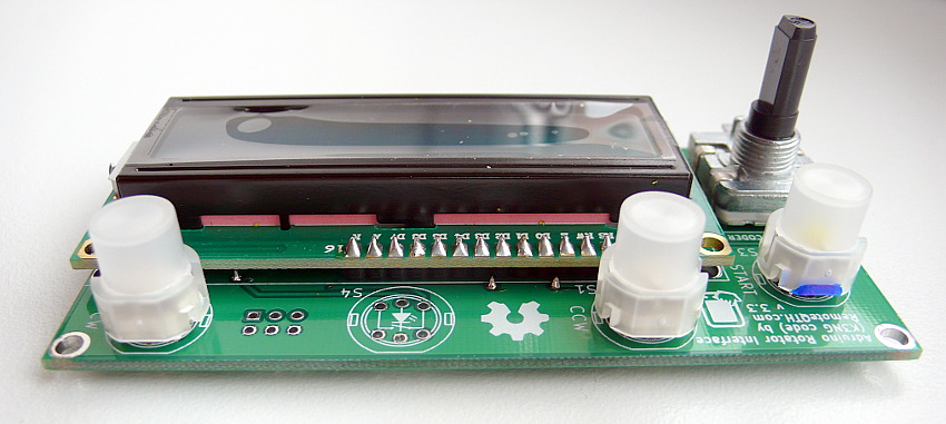
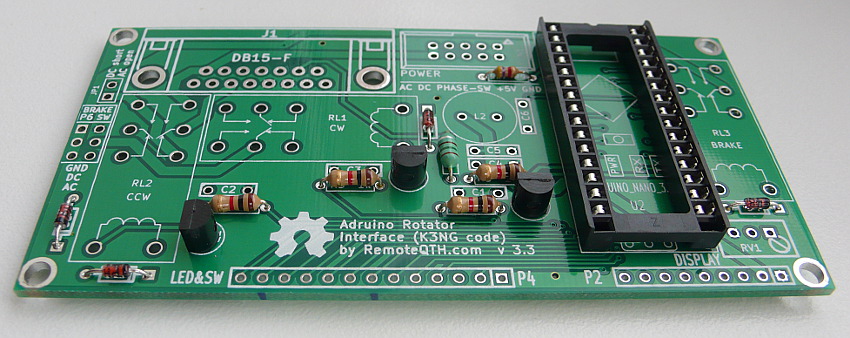
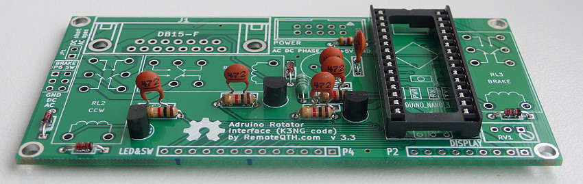
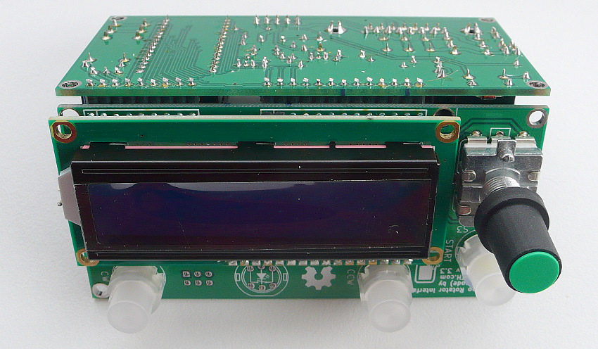
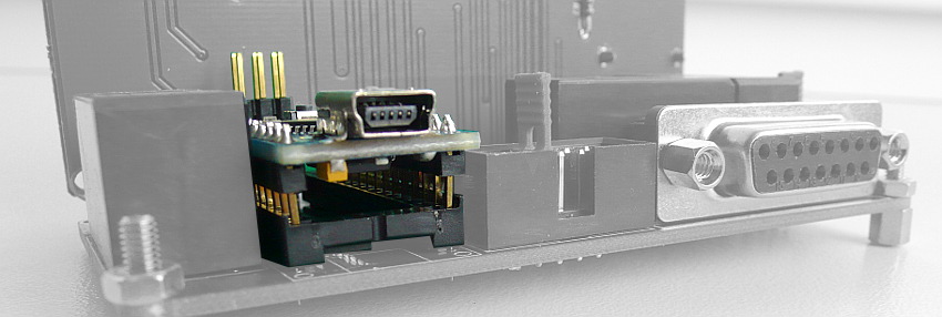
Assembly gallery
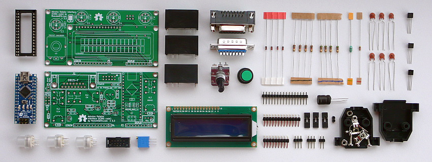
✔ All components
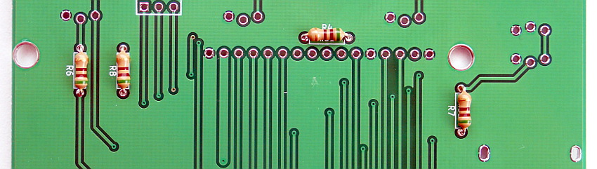
❏ Solder R4 R6 R7 R8 (marked in blue)
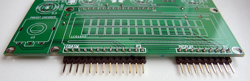
❏ 13 and 9 pins 90° strip
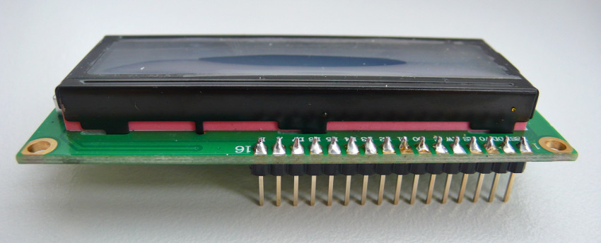
❏ 16 pins strip to LCD
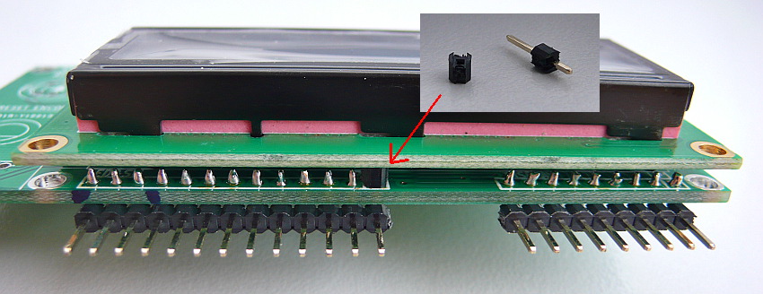
❏ Insulating spacer washers between LCD and PCB
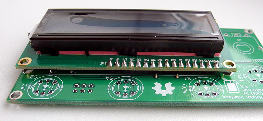
❏ LCD module to PCB
❏ CW, CCW and START switch (marked in blue) and preset encoder, Now front panel is final
❏ Next R1 R2 R3 R5 (marked in black) and R9 solder on main board
❏ D1 D2 D3 D4 (marked in red)
❏ L1 (marked in green) R9 (marked in red)
❏ Q1 Q2 Q3 and Arduino socket
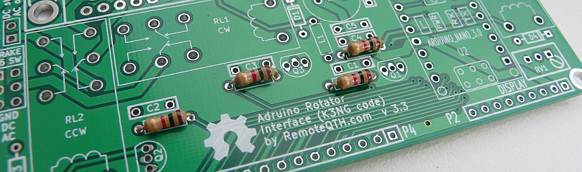
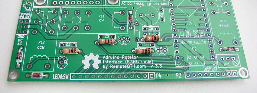
❏ C1 C2 C3 C4 C5 and C6
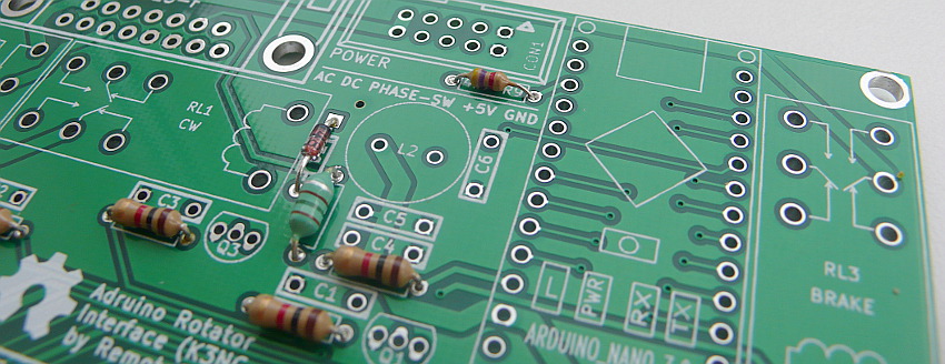
❏ JP1 P6 CON1
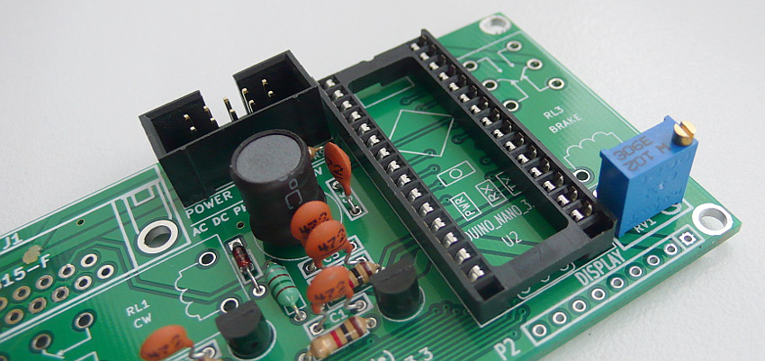
❏ L2 RV1
❏ RL1 RL2 RL3 J1
❏ solder front panel via pin strip
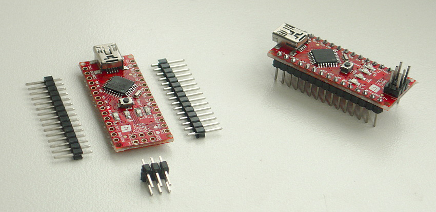
❏ Last solder Arduino Nano pins
❏ Plug Arduino Nano to socket U2
❏ after power up, preset LCD contrast with potentiometer RV1
Firmware
For beginners Getting Started with Arduino
- Download and install Arduino IDE
- Install library
- Download firmware from master tree Web | GitHub.
- requires disable in rotator_features.h (TNX GI1MIC)
#define DEBUG_DUMP
- Or download preconfigured version
- 2019-01-03.zip (TNX GI1MIC)
- 2015-02-24-4RQ.zip - modified version for used with RemoteQTH server web interface.
- 2015-02-24.zip
- 2014-07-08.zip
- 2013-10-26.zip
- Configure by author documentation - contains the settings of your rotator, such as azimuth range, etc.
- Version 2019-01-03 - If do not show degree character (°), change in file rotator_settings.h settings to
#define DISPLAY_DEGREES_STRING "\xB2"
- Version 2015-02-24 - If the LCD displays instead of the character degree (°) lower case "alpha" (α), find in source code all string 'char(223)' and replace to 'char(178)'.''
- Connect USB cable cable between interface and PC
- Select menu Tools/Board:Arduino Nano
- Select menu Tools/Processor: ATmega328P (Old Bootloader)
- Select menu Tools/Port/YOUR-CONNECTED-PORT
- Upload firmware
Third party software
Power
Power inputs are available on both connector CON1 and DB15-J1.
| Power inputs | CON1 | DB15-J1 |
| AC | pin 9+10 | pin 9+10 |
| DC | pin 7+8 | pin 7+8 |
| +5V | pin 3+4 | pin 15 |
| GND | pin 1+2 | pin 5+6 |
- 5V - the entire module can be powered from USB only, but there is a voltage drop, it is better to use an external +5V source, or a DC/DC converter and cut the power to the attached USB cable.
- DC/DC switch add-on for stable 5V power from USB
- CON1 is for power distribution if use with Rapsberry PI gpio board in server.
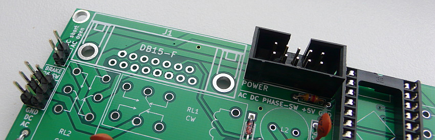
- In sigle interface it is used only phase jumper (Pin 5+6) and short 3+4. All other pins available also in DB15-J1 connector - see on schematics.
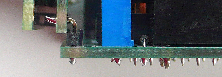
- Pin 3 in CON1 (+5 volts input to supply measure the azimuth)- input stabilized voltage from power board This pin may be short connected (as picture below) with pin4 CON1 (+5 volts to interface), then the voltage measurement uses a common 5V voltage from the power supply module.
Connect DC Rotator (DB15 female) and power inputs

- Need three jumper
- short DC position P6 jumper switch
- short JP1 jumper
- short PHASE-SW pin 5+6 (center) position CON1
- short +5V pin 3+4 CON1
Connect AC Rotator (DB15 female) and power inputs
Diagram for the common AC and +5V ground
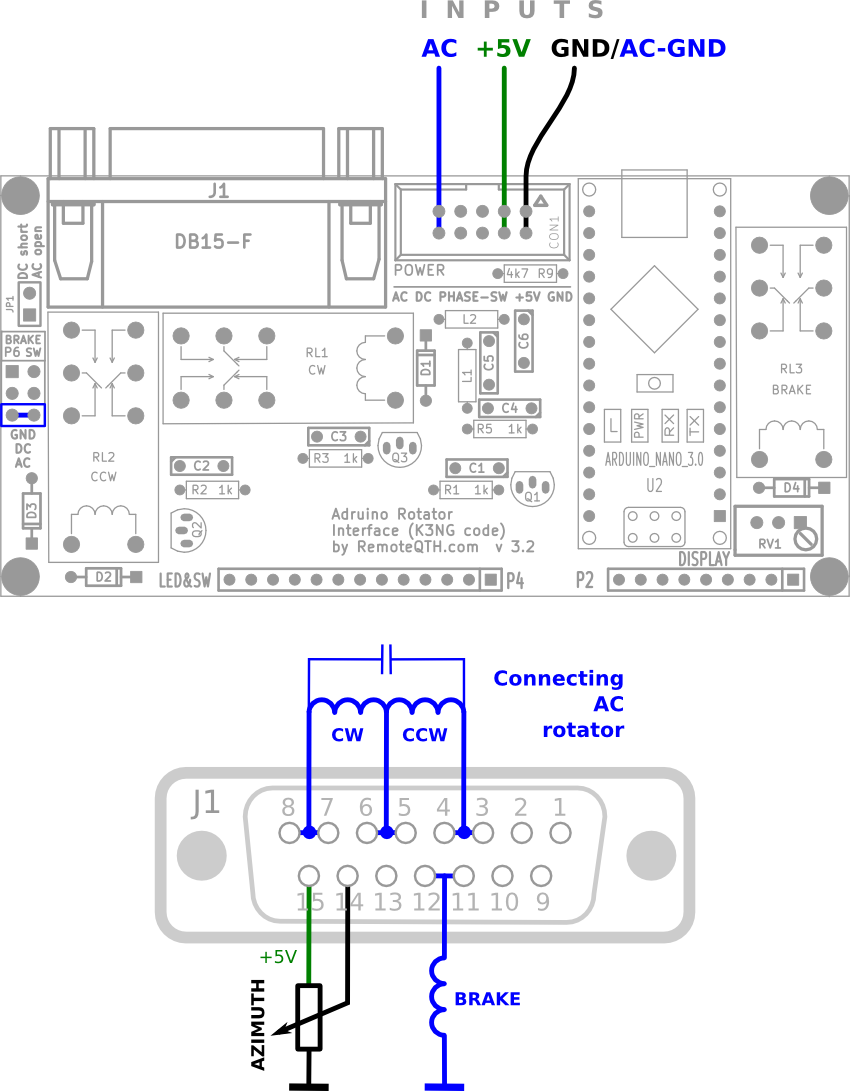
- Need one jumper
- short AC position P6 jumper switch
- short +5V pin 3+4 CON1
Diagram for the different AC and +5V ground

- Need one jumper
- short AC position P6 jumper switch
- short +5V pin 3+4 CON1
Connection examples
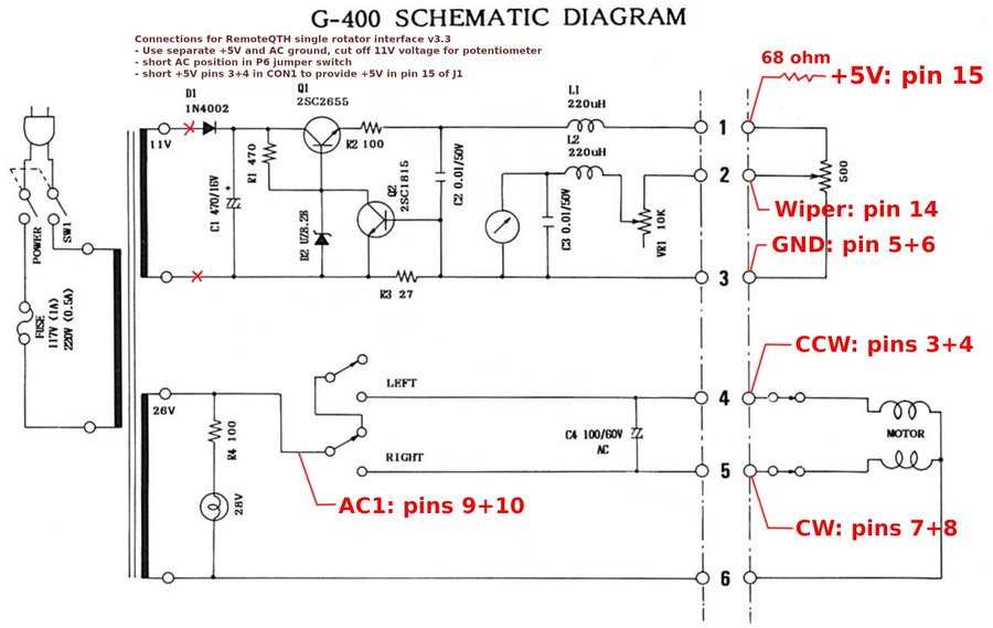
Use with original control box
- OH3BHX firmware for G400RC and connection
- Yaesu G-5400B
- Yaesu G-2800DXA
- DF2LH solution with Kenpro G800-1000SDX
- Yaesu G800
pin DB15      G800 unit
-------------------------
     1+2  ->  5
     3+4  ->  4
      15  ->  1
      14  ->  2
     GND  ->  3
CDE/HyGain HAM IV (grounded center potentiometer)
- Resolving without compromise - mechanically remove grounded center and connect by three wire
- Solutions by VA2NA - external add-on
- Solutions by DM2RM - external add-on
- Add resistor with grounded two wire potentiometer - this solutions produce nonlinearity voltage. You can use calibration table - is not recommended.
Ten turn azimuth potentiometer (one turn used)
- Need negative and positive voltage source
- Set potentiometer bridge from 0 to +5V output
- Left trimmer set a 0V after full CCW rotate
- by right trimmer, set the +5V after full CW rotate
- Repeat until the voltage agree
- Circuit
Control software
- PstRotator for Windows
- RemoteQTH server image for Raspberry PI - web interface
- gRotor
- Even software supporting Yaesu GS-232 protocol...