IP Remote hardware Switch
This revision is from 2015/12/27 00:35. You can Restore it.
The hardware
- Schematics
- PCB
- rev 05 .PNG
- rev 05 .SVG
- 3D View Control 4,5MB
- 3D View Relay 8,5MB
Relay front side

- 1-16 - green LED signalized switched relay.
- white square - sign defines the type of equipment.
Relay back side

- DATA - not used.
- USB - +5V DC POWER supply, or upload arduino firmware (needs open jumper JP5).
- ETHERNET - RJ45 LAN connector.
- OUTPUTS - 14 relay outputs and GND

Control switch

- 1-11 - rotary switch.
- 12-15 - four rock switch with LED.
- 16 - pushbutton.
- LINKED - green LED signalized:
- connect with relay board over IP LAN
- latency (delay) same as LED OFF time.
How to connect
- connect LAN UTP cable direct or via switch (configure connect via internet in a separate chapter)
- plug power via usb mini cable to AC adapter, computer or usb HUB

Network setup
Ethernet module can be configured from a win software, which you can download from our website TCP232-T24, or directly from the manufacturer.
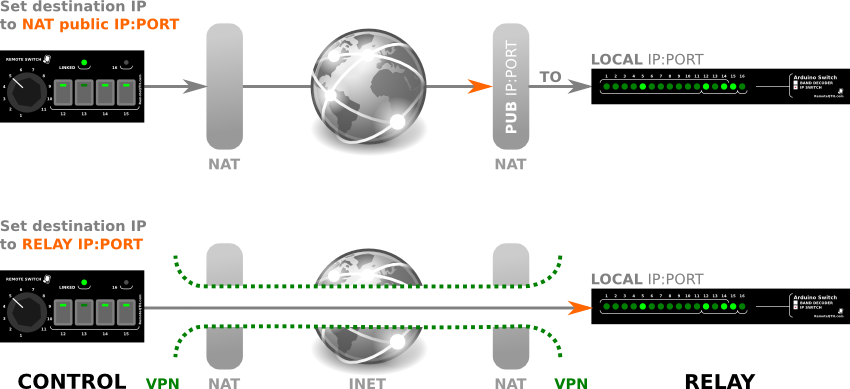
The difference between using NAT and VPN tunel connection.
Firmware
- For beginners Getting Started with Arduino.
- Before uploade new firmware needed
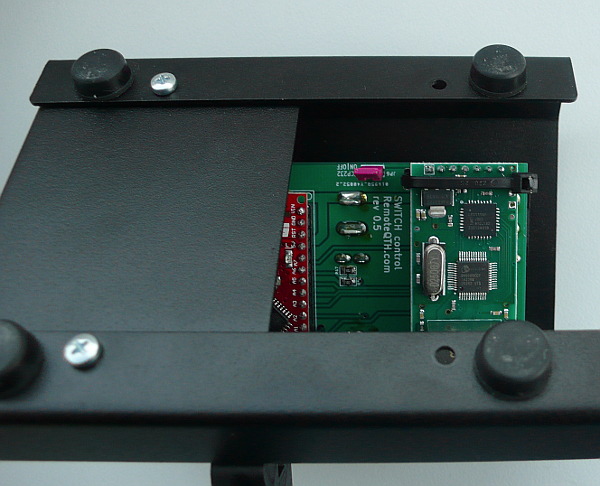
- relay - remove top cover, and open jumper JP5
- control - remove right-bottom cover and open jumper JP6
- After upload set back opened jumpers.
- Source code contains several settings that affect the characteristics of IP Switch.
- #define CONTROL - uncomment activate code for control, comment for relay board.
- #define controlCFG - uncoment enable reconfigurable network - need set configure array (only control).
- #define delayC - default value 2000 ms - time, are waiting for answers, after timeout linked led OFF, and resend data.
- #define delayR - default 10 second - determines the time, after which the relay parking.
- #define parking - default output 11 - 1-11 parking output after timeout - optimally for grounded antenna.