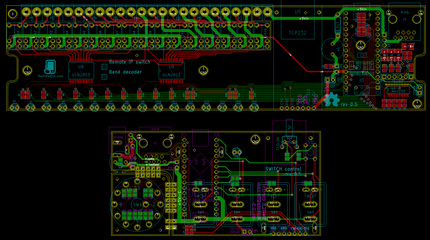
IP Remote hardware Switch
The hardware
- Schematics
- PCB
- rev 05 .PNG
- rev 05 .SVG
- 3D View Control 4,5MB
- 3D View Relay 8,5MB
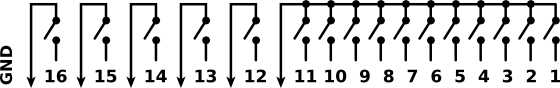
Relay front side
- 1-16 - green LED signalized switched relay.
- white square - sign defines the type of equipment.
Relay back side
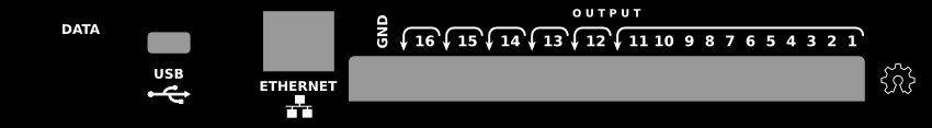
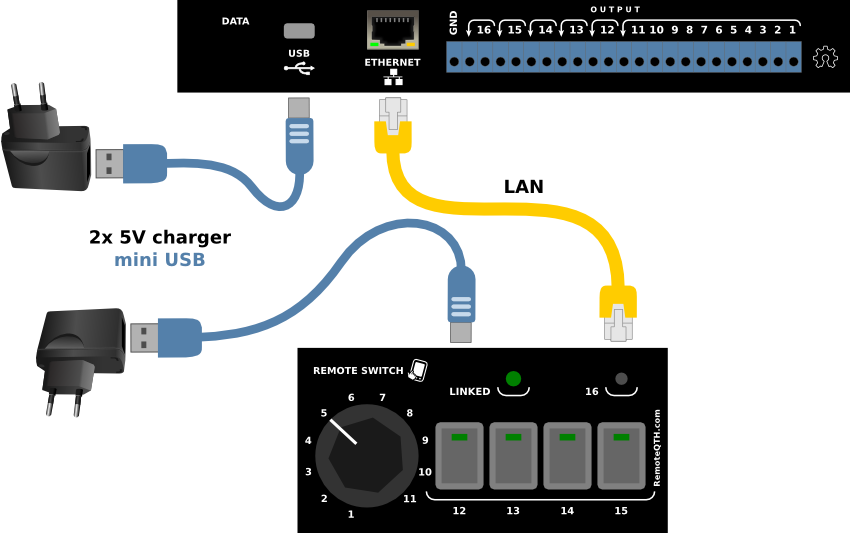
- DATA - not used.
- USB - +5V DC POWER supply, or upload arduino firmware (needs open jumper JP5).
- ETHERNET - RJ45 LAN connector.
- OUTPUTS - 14 relay outputs and GND
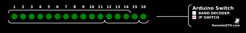
Control switch
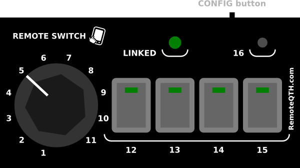
- 1-11 - rotary switch.
- 12-15 - four rock switch with LED.
- 16 - pushbutton.
- LINKED - green LED signalized:
- connect with relay board over IP LAN
- latency (delay) same as LED OFF time.
- CONFIG button need enable in firmware and preset string.
Redirection procedure
- turn the rotary switch to the number that corresponds to the order of relay board, on this you want redirect control
- press the button for three seconds during which the LED goes off
- after LED on release the button
- now wait to the redirection of control - indicated LINK LED on.
How to connect
- connect LAN UTP cable direct or via switch (configure connect via internet in a separate chapter)
- plug power via usb mini cable to AC adapter, computer or usb HUB
Network setup
Ethernet module can be configured from a win software, which you can download from our website TCP232-T24, or directly from the manufacturer.
Default configuration
- Baudrate defines the speed at which communicates Arduino module - default 9600.
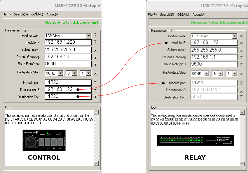
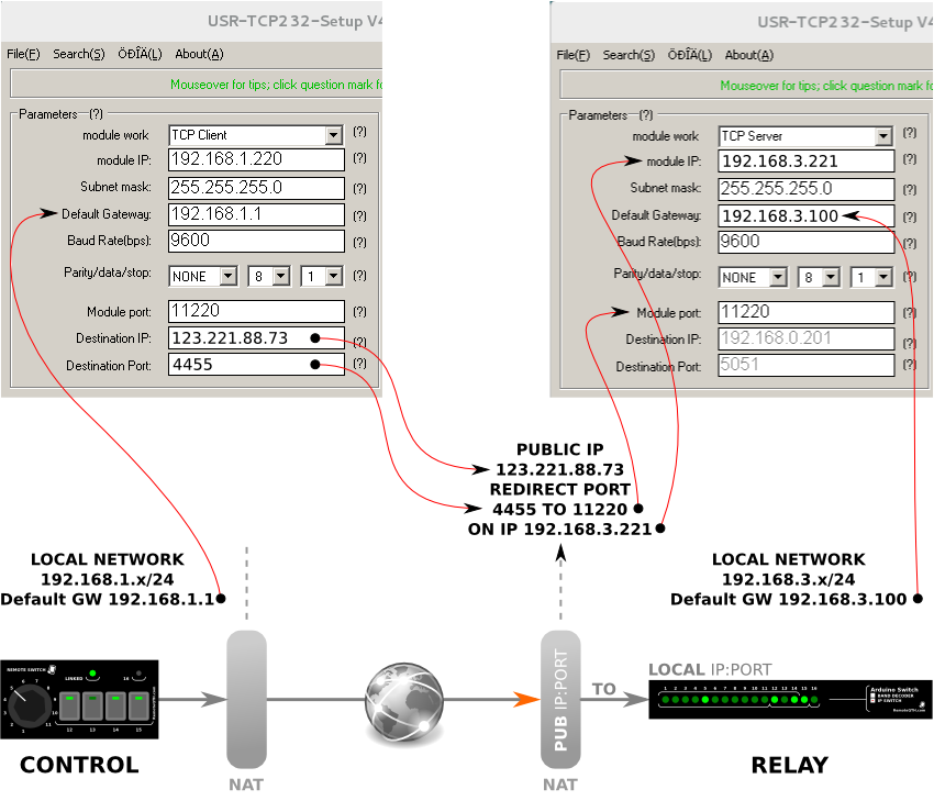
This picture shows default settings ethernet module, similar settings will suffice for the local network, or VPN tunnels. Connect over the internet with a public IP address remote side, need change other IP settings, is depending on individual networks, public IP address and port redirected. The difference between using NAT and VPN tunel connection shows next picture.
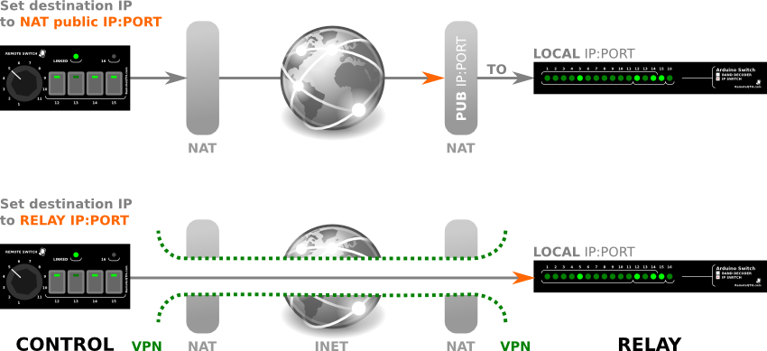
Example setting connection via internet
Firmware
- For beginners Getting Started with Arduino.
- Before uploade new firmware needed
- relay - remove top cover, and open jumper JP5
- control - remove right-bottom cover and open jumper JP6
- After upload set back opened jumpers.
- Source code contains several settings that affect the characteristics of IP Switch.
- #define CONTROL - uncomment activate code for control, comment for relay board.
- #define controlCFG - uncoment enable reconfigurable network - need set configure array (only control).
- #define fullBits - disable one from 11 filter = use full range bits
- #define delayC - default value 2000 ms - time, are waiting for answers, after timeout linked led OFF, and resend data.
- #define delayR - default 10 second - determines the time, after which the relay parking.
- #define parking - default output 11 - 1-11 parking output after timeout - optimally for grounded antenna.
How to create configure string
for reconfigure network from control box must be read from oficial config software. After sets all value and press Setup via NET software set the ethernet module and show in left bottom window configuration string containing thirty-one two-digit hexadecimal digits - these numbers will add a 0x and transcripts to the program source code.
/* 1 */ {0x55, 0xBA, 0xDD, 0x01, 0xA8, 0xC0, 0xD4, 0x2B, 0xDC, 0x01, 0xA8, 0xC0, 0xD4, 0x2B, 0x01, 0x01, 0xA8, 0xC0, 0x01, 0x80, 0x25, 0x00, 0x03, 0x00, 0x00, 0x04, 0x00, 0xFF, 0xFF, 0xFF, 0x9D }, // 192.168.1.221 We have a total of eleven pre-set configurations ethernet module.