Open interface III
This revision is from 2017/01/08 01:47. You can Restore it.
Interface device between computer and transceiver - accesses all controls, CAT and audio to PC.
Main function
- Completly Open source
- Hardware and software is open (cc by-sa)
- You can modify or build own software functionality
- Arduino compatible chip (ATMEGA2560)
- Operation system independent (Linux, OSX, Windows)
- CW - complete K3NG code
- CLI interface (telnet) or Winkey emulation
- Memory button
- Speed rotary encoder
- Keying from PC com port (DTR/RTS)
- SSB
- Switch TX audio between Microphone (Foot switch PTT) and USB Audio (com PTT)
- Playing audio memory from PC
- FSK (RTTY)
- from three source
- Serial com port (DTR/RTS) - EXTFSK
- Serial com port ASCII (telnet)
- Three button memories
- Sidetone
- Decoding TX signal during transmit from EXTFSK
- DIGI Modes
- Adjust TX volume buttons
- Adjust RX volume potentiometer
- Isolated audio path with two transformers
- CAT
- Support TTL (Icom) and 232 level (Kenwood, Yaesu)
- Own serial to USB interface with internal USB HUB
- Band decoder
- Support Icom, Kenwood, Yaesu CAT
- Sniffing TRX to PC communications or automatically own request
- Outputs
- TTL level BCD
- CAT on ACC connector - CI-V, Kenwood/Yaesu (need TTL/232 converter)
- IP output (in future)
- OTHER
- Galvanically isolated USB to PC - four independent ground
- PC
- Transceiver
- RX audio
- TX audio
- micro SD card slot for future use (save config)
- Ethernet module
- two type PA PTT output
- Relay - isolated but 5ms latency
- Open collector - quick
- ACC connector (HDMI type) with
- Serial line
- I2C
- PWM
- Analog inputs
- Digital in/out
The hardware
Front side
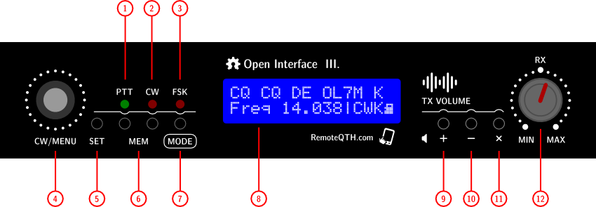
- 1 - PTT LED - shows the activation of one of the PTT outputs (PTT1, PTT2, PTT-SSB, PA-PTT)
- 2 - CW LED - shows the activation of one of two CW outputs (CW1, CW-232)
- 3 - FSK LED - shows the activation of one of two FSK outputs (FSK-Arduino, FSK-232)
- 4 - Rotary encoder - change WPM speed in CWK and CWD MODE, and select MENU in other mode
- 5 - SET/MEM 0 button - has functions depending on the selected MODE
- in CWD and CWK MODE activate/deactivate Command mode
- in FSK MODE activate transmit Memory-0
- 6 - MEM 1-2 button - in CWD CWK FSK MODE activate two memories
- 7 - MODE button
- Short press MODE changes in the order |CWK >CWD |SSB >FSK |FSK |DIG
- Long press activate MENU on LCD. In the menu, move with the rotary encoder or short press MODE button. Return change after 3 seconds without change change
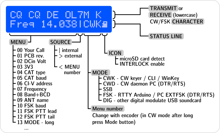
- 8 - LCD display
- First line show
- transmiting CW character
- transmiting RTTY character from Arduino uppercase
- transmiting RTTY character from PC lowercase
- Second line show
- First eleven characters - selected MENU
- Second four characters - active MODE or numbers MENU
- Last characters - show microSD card icon, if pluged
- 9 - TX audio + button - volume UP
- 10 - TX audio - button - volume DOWN
- 11 - TX audio mute button - MUTE
- 12 - RX volume potentiometer - receiving signal level
Rear side
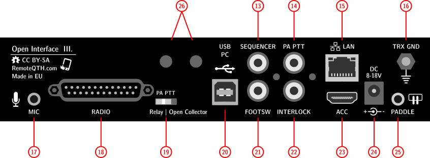
- 13 - SEQUENCER output CINCH - open collector (MAX 50V/500mA)
- 14 - PA-PTT output CINCH - dependency to rear PA PTT switch
- Open collector (MAX 50V/500mA)
- Relay (MAX 0,5A/125V AC, or 1A/24V DC)
- 15 - LAN - RJ45 connector - (if Ethernet optional module installed)
- 16 - TRX GND - M4 screw
- 17 - MIC - Jack 3,5mm - microphone input - need preset input switch, dependency on type microphone used
- Dynamic microphone - JP7 open
- Electret microphone - JP7 short
- 18 - RADIO - D-SUB 25 pin female connector Pin connection
- 19 - PA PTT - manual switch - select what circuit will be switch PA-PTT output (CINCH and pin7 in RADIO connector)
- 20 - PC USB - USBB type connector for PC, with isolated ground
- 21 - FOOT SWITCH - CINCH - SSB PTT input is activated by grounding center pin
- 22 - INTERLOCK - CINCH - input is activated by grounding center pin
- 23 - ACC - HDMI type - by default blinded Pin connection
- 24 - POWER - input - DC jack 2,1/5,5mm diameter to connect input power 8-18V DC (center positive)
- 25 - PADDLE - input - activated by grounding pin
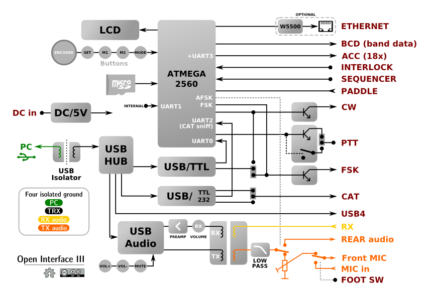
Block diagram
Board jumper preset
- JP4 - DTR to CW/FSK
- JP3 - Auto reset ON - enabling reset from serial DTR pin to Arduino
- JP5 - Self reset ON - allows Arduino self reset from D39 output (not use)
- JP10 - CAT Icom/Other - select between Icom CI-V and other TRX bus
- JP7 - DC to MIC - allows DC voltagefrom TRX to your microphone
- OPEN for dynamic microphone
- SHORT for elecret microphone
- P5 - CAT TTL/232 - select between two logical level
- 5V TTL
- +-12V RS232
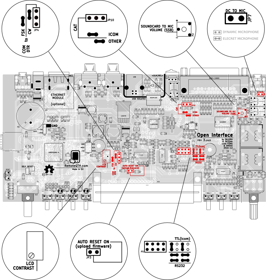
Board adjust
- P4 - LCD contrast potentiometer
- P2 - TX USB souncard to front Microphone volume potentiometer adjust transmit audio volume if activate MODE SSB. Suitable for playing voice memory.
Internal connectors
Hardware dependency
| Mode | Source | Outs | ||
| PTT | CW/FSK | WINKEY | AFSK | |
| CWK - CW keyer | PTT1 | CW1/2 | HIGH | LOW |
| >CWD - CW daemon (PC) | RTS | DTR* | LOW | LOW |
| SSB - LSB-USB-FM | RTS/FootSW | - | LOW | LOW |
| >FSK - EXTFSK | RTS | DTR* | LOW | LOW |
| FSK - Serial ascii | PTT1 | Serial | HIGH | LOW |
| DIG - USB audio codec (AFSK) | RTS | - | LOW | HIGH |
* JP4 jumper must be set CW or FSK
Note - character ">" shown external signal source
- WINKEY HIGH - disable DTR/RTS
- AFSK HIGH - switch TX audio path
Problems
- Disconnecting the USB causes high potential (measured 80V AC) between USB-GND and GND-TRX, is usually enough:
- Grounded case
- Replace the power supply (not the male switched adapter without grounding pin in the drawer)
Firmware
LCD
Because firmware open, LCD show dependency to use firmware.
- First line show
- TX signal in CW and FSK mode
- RX sniffing decode RTTY (lowercase) during keying from PC
- Second status line show
- MENU
- Source keying
- MODE
- microSD card icon, if insert
Modes
- |CWK - CW Keyer by K3NG
- WinKey/CLI emulation
- SOURCE: USB/Serial interface
- INPUTS: Paddle Interlock Encoder Set/Mem_buttons
- OUTPUTS: CW1/2 PTT1/2
- >CWD - CW Daemon
- Keyng from PC
- SOURCE: USB/Serial interface DTR/RTS
- INPUTS: DTR(CW) RTS(PTT)
- OUTPUTS: CW1 PTT1
- |SSB - SSB
- LSB USB AM FM
- SOURCE: Mic-audio
- INPUTS: FootSwitch RTS
- OUTPUTS: PTT1
- >FSK - PC FSK keying
- RTTY keying from EXTFSK with sniffing and decode signal (lowercase) by JI3BNB / OK1HRA
- SOURCE: USB/Serial interface, Memory0-2_button
- INPUTS: DTR RTS
- OUTPUTS: PTT1 FSK
- |FSK generator by JI3BNB
- generator from Serial ASCII
- SOURCE: USB/Serial interface
- INPUTS: ASCII, Memory0-2_button
- OUTPUTS: PTT1 FSK
- |DIG - Audio FSK
- AFSK PSK and any modes modulate fom audio
- SOURCE: USB souncard
- INPUTS: RTS(PTT)
- OUTPUTS: PTT
Pinouts
RADIO 25 pin D-SUB
| pin-1 | in | Input power 8-18V DC from Transceiver |
| pin-2 | out | CAT TXD / CI-V |
| pin-3 | out | USB4 +5V output |
| pin-4 | USB4 -Data | |
| pin-5 | out | BCD4 output TTL |
| pin-6 | out | BCD2 output TTL |
| pin-7 | out | PA PTT |
| pin-8 | out | PTT1 |
| pin-9 | out | CW1 |
| pin-10 | out | FSK |
| pin-11 | out | Microphone (TX) |
| pin-12 | out | TX audio |
| pin-13 | out | RX audio |
| pin-14 | Transceiver GND | |
| pin-15 | in | CAT RXD |
| pin-16 | USB4 +Data | |
| pin-17 | TRX GND | |
| pin-18 | out | BCD3 output TTL |
| pin-19 | out | BCD1 output TTL |
| pin-20 | out | PTT2 |
| pin-21 | out | CW2 |
| pin-22 | out | PTT Microphone |
| pin-23 | in | Interlock |
| pin-24 | TX audio GND | |
| pin-25 | RX audio GND | |
| shield | Transceiver GND |
Accessory connector (HDMI)
WARNING - All ACC signals directly connect to ATMEGA chip without some ESD protection. Before use strongly recomended protect this lines.
| ACC-1 | RXD | Serial3 |
| ACC-2 | GND | |
| ACC-3 | TXD | Serial3 |
| ACC-4 | D47 | |
| ACC-5 | D13 | PWM |
| ACC-6 | D5 | PWM |
| ACC-7 | D30 | |
| ACC-8 | D32 | |
| ACC-9 | D11 | PWM |
| ACC-10 | D12 | PWM |
| ACC-11 | D38 | |
| ACC-12 | A2 | |
| ACC-13 | A3 | |
| ACC-14 | A8 | |
| ACC-15 | SCL | I2C |
| ACC-16 | SDA | I2C |
| ACC-17 | A9 | |
| ACC-18 | +5V | |
| ACC-19 | A11 | |
| ACC-20 | GND |
ATMEGA-2560 pinout (rev 3.1415)
| Arduino pins | connect to | in/out | Note |
| RX0 | USB | in | Connect to USB/serial interface |
| TX0 | USB | out | use for command CW keyer or firmware upload |
| D2 | Interlock | in | pull-up external, Interrupt 0 |
| D3 | PTT-232 | in | pull-up external, Interrupt 1 |
| D4 | CW tone | out | |
| D5 | ACC pin6 | PWM | |
| D6 | LCD-D4 | out | |
| D7 | LCD-D5 | out | |
| D8 | LCD-D6 | out | |
| D9 | LCD-D7 | out | |
| D10 | Ethernet SCS | out | |
| D11 | ACC pin9 | PWM | |
| D12 | ACC pin10 | PWM | |
| D13 | ACC pin5 | PWM | |
| TX3 | ACC pin3 | out | + Internal pins |
| RX3 | ACC pin1 | in | + Internal pins |
| TX2 | CAT | out | Connected in parallel to USB/serial CAT interface |
| RX2 | CAT | in | use for CAT sniffing or TX request |
| D18 | Encoder-B | in | pull-up internal (optional external*), Interrupt 5 (TX1) |
| D19 | PTT foot | in | pull-up external, Interrupt 4 (RX1) |
| D20 | SDA - ACC pin16 | in/out | I2C, Interrupt 3 |
| D21 | SCL - ACC pin15 | out | I2C, Interrupt 2 |
| D22 | PTT2 | out | |
| D23 | FSK | out | keying from arduino |
| D24 | Encoder-A | in | pull-up internal (optional external*) |
| D25 | PTT3 | out | |
| D26 | paddle Left | in | pull-up external |
| D27 | WinKey | out | HIGH if CW keying running (disable DTR/RTS) |
| D28 | paddle Right | in | pull-up external |
| D29 | AFSK | out | HIGH if AFSK keying (switch TX audio path) |
| D30 | ACC pin7 | ||
| D31 | PTT-PA | out | |
| D32 | ACC pin8 | ||
| D33 | FSK detector | in | pull-up external |
| D34 | CW1 | out | |
| D35 | CW2 | out | |
| D36 | MENU | in | pull-up external |
| D37 | LCD-E | out | |
| D38 | ACC pin11 | ||
| D39 | self reset | out | HIGH (enable with jumper JP5) |
| D40 | Sequencer | out | |
| D41 | PTT1 | out | |
| D42 | BCD1 | out | TTL Band data |
| D43 | BCD2 | out | TTL Band data |
| D44 | BCD3 | out | TTL Band data |
| D45 | BCD4 | out | TTL Band data |
| D46 | Ethernet detect | in | pull-up internal |
| D47 | ACC pin4 | ||
| D48 | Internal SMT pad | Free | |
| D49 | Internal SMT pad | Free | |
| D50 | MISO | out | |
| D51 | MOSI | out | |
| D52 | SCK | out | |
| D53 | microSD CS | out | |
| A0 | Internal SMT pad | Free | |
| A1 | CW keyer Memory button | in | pull-up external |
| A2 | LCD-RS | out | |
| A3 | ACC pin12 | ||
| A4 | ACC pin13 | ||
| A5 | microSD plug | in | pull-up internal |
| A6 | measure 3.3V | in | |
| A7 | measure input voltage | in | coefficient 11 |
| A8 | ACC pin14 | ||
| A9 | ACC pin17 | ||
| A10 | - | Free | |
| A11 | ACC pin19 | ||
| A12 | - | Free | |
| A13 | - | Free | |
| A14 | - | Free | |
| A15 | - | Free |
- If RC circuits installed