Open interface III
<<- Web pageInterface device between computer and transceiver - accesses all controls, CAT and audio to PC.
Expansion device
- ACC keyboard - control for IP switch
- Outdoor GPS
ToDo
- Cable wiring circuits
- ACC expander
- Firmware
- control external IP relay from band decoder
- control external IP rotator
Quick Start Guide
- Download config from GitHub, write to microSD card and put to OpenInterface from left side
- Optional solder encoder debouncing R/C - see schematics (with drill two bridge PCB vias)
- Make wiring connect to your TRX
- Preset board jumpers
- Install ethernet module (optional)
- Connect power supply (if not powered from TRX)
- Preset firmware and upload
- ⚠ TIP Some setinngs you can live change from menu, how ths work?
- If mode is CW, rotary encoder set primary WPM speed. For activate menu long press MODE buton. This will be show with < character and menu number - rotary encoder now change menu. After some second without change menu deactivate.
- If mode is not a CW encoder directly chenge menu.
- After selected you can change value (only part of the menu) with short press MODE buton again. This will be sign with <+-, and now you can change value (for example PTT lead menu 16).
- Deactivate change value with short press MODE again.
- ⚠ Powered ON only after connect all cables
Main function
- Completly Open source
- Hardware and software is open (cc by-sa)
- You can modify or build own software functionality
- Arduino compatible chip (ATMEGA2560)
- Operation system independent (Linux, OSX, Windows)
- CW - complete K3NG code
- CLI interface (telnet) or Winkey emulation
- Memory button
- Speed rotary encoder
- Keying from PC com port (DTR/RTS)
- SSB
- Switch TX audio between Microphone (Foot switch PTT) and USB Audio (com PTT)
- Playing audio memory from PC
- FSK (RTTY)
- from three source
- Serial com port (DTR/RTS) - EXTFSK
- Serial com port ASCII (telnet)
- Three button memories
- Sidetone
- Decoding TX signal during transmit from EXTFSK
- DIGI Modes
- Adjust TX volume buttons
- Adjust RX volume potentiometer
- Isolated audio path with two transformers
- CAT
- Support TTL (Icom) and 232 level (Kenwood, Yaesu)
- Own serial to USB interface with internal USB HUB
- Band decoder
- Support Icom, Kenwood, Yaesu CAT
- Sniffing TRX to PC communications or automatically own request
- Outputs
- TTL level BCD
- CAT on ACC connector - CI-V, Kenwood/Yaesu (need TTL/232 converter)
- IP output (in future)
- OTHER
- INTERLOCK - switches OFF all PTT signals, defined by Sequencer delay
- Galvanically isolated USB to PC - four independent ground
- PC
- Transceiver
- RX audio
- TX audio
- micro SD card slot for future use (save config)
- Ethernet module
- two type PA PTT output
- Relay - isolated but 5ms latency
- Open collector - quick
- ACC connector (HDMI type) with
- Serial line
- I2C
- PWM
- Analog inputs
- Digital in/out
The hardware
Front side
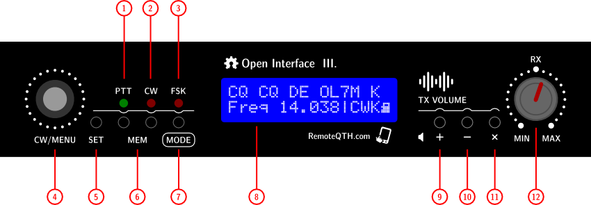
- 1 - PTT LED - shows the activation PA PTT output (no activate from PTT1, PTT2 orPTT-SSB)
- 2 - CW LED - shows the activation of one of two CW outputs (CW1, CW-232)
- 3 - FSK LED - shows the activation of one of two FSK outputs (FSK-Arduino, FSK-232)
- 4 - Rotary encoder - change WPM speed in CWK and CWD MODE, and select MENU in other mode
- 5 - SET/MEM 0 button - has functions depending on the selected MODE
- in CWD and CWK MODE activate/deactivate Command mode
- in FSK MODE activate transmit Memory-0
- 6 - MEM 1-2 button - in CWD CWK FSK MODE activate two memories
- 7 - MODE button
- Short press MODE changes in the order |CWK >CWD |SSB >FSK |FSK |DIG
- Long press activate MENU on LCD. In the menu, move with the rotary encoder or short press MODE button. Return change after 3 seconds without change
- 8 - LCD display
- First line show
- transmiting CW character
- transmiting RTTY character from Arduino uppercase
- transmiting RTTY character from PC lowercase
- Second line show
- First eleven characters - selected MENU
- Second four characters - active MODE or numbers MENU
- Last characters - show microSD card icon, if pluged
- 9 - TX audio + button - volume UP
- 10 - TX audio - button - volume DOWN
- 11 - TX audio mute button - MUTE
- 12 - RX volume potentiometer - receiving signal level
Rear side
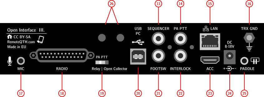
- 13 - SEQUENCER output CINCH - open collector (MAX 50V/500mA)
- 14 - PA-PTT output CINCH - dependency to rear PA PTT switch
- Open collector (MAX 50V/500mA)
- Relay (MAX 0,5A/125V AC, or 1A/24V DC)
- 15 - LAN - RJ45 connector - (if Ethernet optional module installed)
- 16 - TRX GND - M4 screw
- 17 - MIC - Jack 3,5mm - microphone input - need preset input switch, dependency on type microphone used
- Dynamic microphone - JP7 open
- Electret microphone - JP7 short
- 18 - RADIO - D-SUB 25 pin female connector Pin connection
- 19 - PA PTT - manual switch - select what circuit will be switch PA-PTT output (CINCH and pin7 in RADIO connector)
- Open collector (MAX 50V/500mA)
- Relay (MAX 0,5A/125V AC, or 1A/24V DC)
- 20 - PC USB - USB B type connector for PC, with isolated ground
- 21 - FOOT SWITCH - CINCH - SSB PTT input is activated by grounding center pin
- 22 - INTERLOCK - CINCH - input is activated by grounding center pin - switches OFF all PTT signals, defined by Sequencer delay
- 23 - ACC - HDMI type - by default blinded Read warning first!
- 24 - POWER - input - DC jack 2,1/5,5mm diameter to connect input power 8-18V DC (center positive) with consumption 160mA/12V
- 25 - PADDLE - input - Pinout
- 26 - HOLES - mount two optional switches, connect to any internal jumper on board - for example enable reset (JP3), or DTR to CW/FSK (JP4)
Left side
- microSD card slot
- RESET button
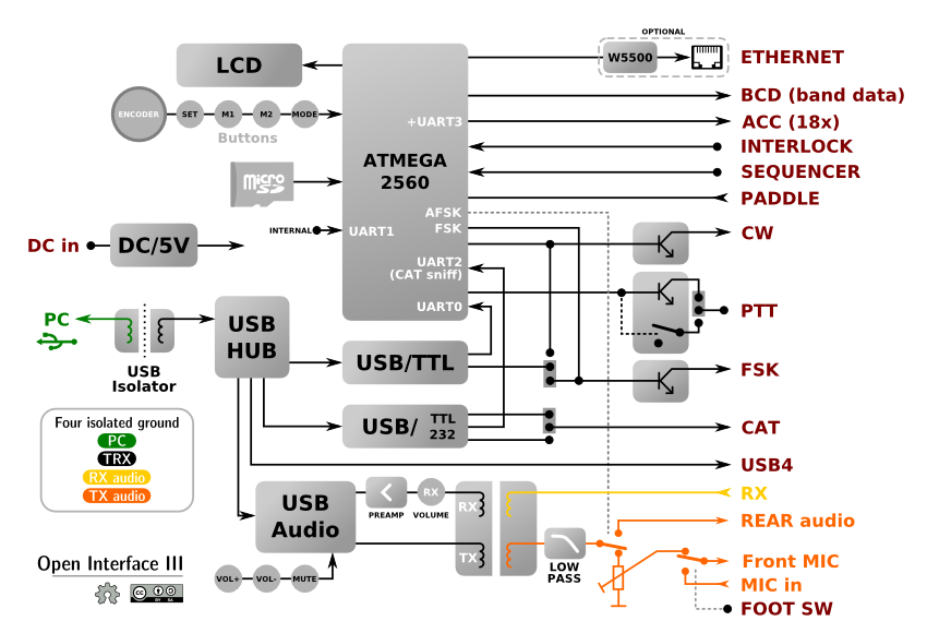
Block diagram
Circuits
How to open the enclosure box
- Unscrew
- two screws on the rear side, near RCA connector
- three screws on the left side
- three screws on the right side
- When closing proceed in the reverse order
Board jumper preset
First you have to open the enclosure box
- JP4 - DTR to CW/FSK - select DTR output from USB/serial interface to activate keying CW or FSK output
- JP3 - Auto reset ON - enabling reset from serial DTR pin to Arduino
- SHORT - enable - need only for upload firmware
- OPEN - disable - standard operation
- JP5 - Self reset ON - allows Arduino self reset from D39 output (not use)
- by default OPEN
- JP10 - CAT Icom/Other - select between Icom CI-V and other TRX bus
- Icom - left
- Other TRX - right
- JP7 - DC to MIC - allows DC voltage from TRX to your microphone
- OPEN for dynamic microphone
- SHORT for elecret microphone
- P5 - CAT TTL/232 - select between two logical level
- 5V TTL - ICOM
- +-12V RS232
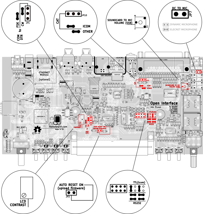
Board adjust
- P4 - LCD contrast potentiometer
- P2 - TX USB souncard to front Microphone volume potentiometer adjust transmit audio volume if activate MODE SSB. Suitable for playing voice memory.
How to install Ethernet module
Compatible with ethernet module USR-ES1 (datasheet)
- Turn power OFF
- Open the enclosure box
- Plug module to U9 pin strip
- Break out with a knife or thin screwdriver blind and open for RJ49 ethernet connector in rear side of box.
- Configure firmware for Ethernet module
- Short JP3 jumper before upload
- Close enclosure
Internal connectors
- K2 - ATmega Serial3 UART (5V) RXD, TXD, GND
- P7 - ICSP connector for directly programing ATmega chip - need for upload bootloader contains GND RESET MOSI SCK +5V MISO
- P9 - free USB4 output from USB hub - same signal available on rear DB-25 connector
Not staffed parts
- R6 package 0805 - activate voltage divider with R9, can reduce audio signal output level
- C71 package C - will increase RX audio preamp gain
- C50 package 0805 - activate Left channel output (TX) from USB sound card
- D15, D16, D17 package 0805 - always activate PA PTT output (solved in firmware via sequencer function)
- JP1 two pin jumper - short on PCB
Hardware dependency
| Mode | Source | Outs | ||
| PTT | CW/FSK | WINKEY | AFSK | |
| CWK - CW keyer | PTT1 | CW1/2 | HIGH | LOW |
| >CWD - CW daemon (PC) | RTS | DTR* | LOW | LOW |
| SSB - LSB-USB-FM | RTS/FootSW | - | LOW | LOW |
| >FSK - EXTFSK | RTS | DTR* | LOW | LOW |
| FSK - Serial ascii | PTT1 | Serial | HIGH | LOW |
| DIG - USB audio codec (AFSK) | RTS | - | LOW | HIGH |
* JP4 jumper must be set CW or FSK
Note - character ">" shown external signal source
- WINKEY HIGH - disable DTR/RTS
- AFSK HIGH - switch TX audio path
Problems
- Disconnecting the USB causes high potential (measured 80V AC) between USB-GND and GND-TRX, is usually enough:
- Grounded case
- Replace the power supply (not the male switched adapter without grounding pin in the drawer)
Firmware
For beginners Getting Started with Arduino
This manual describes the function of the modified firmware from K3NG, which in addition includes:
- Switch MODE - preset board for each mode separately
- MENU - show many actual value and firmware preset
- Band decoder - sniffing CAT or generate own request for read frequency, with BCD (IP in future) output
- FSK keying - RTTY keying from memory button or serial line
- FSK decode - RTTY decode signal generate from PC (EXTFSK)
Download
available on github
- if install Ethernet module hardware, need copy Ethernet2 library to arduino IDE
- and before upload change timeout in Dhcp.h file from
int beginWithDHCP(uint8_t *, unsigned long timeout = 60000, unsigned long responseTimeout = 5000);
toint beginWithDHCP(uint8_t *, unsigned long timeout = 6000, unsigned long responseTimeout = 5000);
Configure
- CW keyer functionality configure in external files same as in original K3NG code (manual)
- Other function configure in master .ino file from line 1198
- how to upload
WinTest
Need enable line
#define OPTION_WINKEY_2_HOST_CLOSE_NO_SERIAL_PORT_RESET
in file keyer_features_and_options_open_interface.h
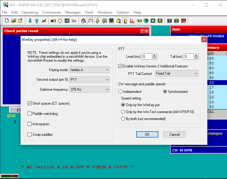
Tested version 4.24.0-DXP
N1MM
Need enable line
#define OPTION_WINKEY_2_HOST_CLOSE_NO_SERIAL_PORT_RESET
in file keyer_features_and_options_open_interface.h
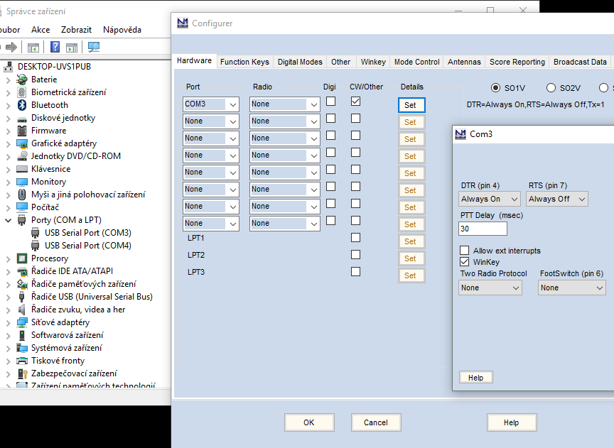
Tested version 1.0.6164.0
PTT TRX
For TRX you can configure one from three PTT outputs for each mode seperatly
- PTT1 - pin 8 on DB25
- PTT2 - pin 20 on DB25
- PTT3(mic) - pin 22 on DB25 (typicaly for front mic PTT)
Firmware configure section:
                                      // 1 = pin8 at DB25 | 2 = pin20 at DB25 | 3 = pin22 at DB25
 #define PTTmodeCW    1               // [1-3] How PTT TRX output use in mode CW
 #define PTTmodeSSB   3               // [1-3] How PTT TRX output use in mode SSB
 #define PTTmodeFSK   1               // [1-3] How PTT TRX output use in mode FSK
 #define PTTmodeDIGI  2               // [1-3] How PTT TRX output use in mode DIGI(AFSK)
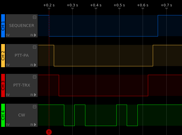
Sequencer
controled four outputs in precise seqenced time
- SEQUENCER - RCA cinch on rear panel
- PTT-PA - RCA cinch on rear panel + pin7 in DB25
- PTT-TRX - one from three PTT outputs, see previous section
#define SEQUENCERlead  0             // SEQUENCER output lead delay ms between SEQ-->PA
#define SEQUENCERtail  200           // SEQUENCER output tail delay ms          :    :                      :     PA-->SEQ
#define PAlead         10            // PA output lead delay ms between         :    PA-->TRX               :     :    :
#define PAtail         200           // PA output tail delay ms                 :    :    :                 TRX-->PA   :
#define PTTlead        10            // PTT (FSK) lead delay ms between         :    :    TRX-->FSK         :     :    :
#define PTTtail        350           // PTT (FSK) tail delay ms                 :    :    :           FSK-->TRX   :    :
/*                     |                                                                                     ^
                    Master                                  SEQUENCERlead ______|    |    |            |    |     |_____ SEQUENCERtail
                    for CW                                         PAlead ___________|    |            |    |___________ PAtail
                   tail delay                                     PTTlead ________________|            |________________ PTTtail
Ethernet
- Enable
#define ETHERNET_MODULE // enable ETHERNET module (must be installed) EXPERIMENTAL
- DHCP
#define __USE_DHCP__ // Uncoment to Enable DHCP
- Fixed IP
IPAddress ip(192, 168, 1, 220);         // IP
IPAddress gateway(192, 168, 1, 200);    // GATE
IPAddress subnet(255, 255, 255, 0);     // MASK
IPAddress myDns(8, 8, 8, 8);            // DNS (google pub)
Incoming UDP command
- FSK ASCII
#define UDP_RTTY_PORT 89 // UDP port listen to RTTY character (FSK mode)
- Commands
#define UDP_COMMAND_PORT 88      // UDP port listen to command EXPERIMENTAL!
                                 // m:#;   - Mode # 0-5
                                 // i:#;   - INTERLOCK # 0/1 (on/off)
                                 // p:#:%; - PTT # 0/1 (on/off), % 0-3 (0=PTTPA, 1=PTT1, 2=PTT2, 3=PTT3)
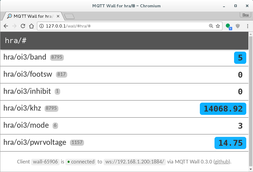
MQTT
#define MQTT_PATH "oi3"          // Identificator your device in MQTT
#define MQTT_PORT 1883           // MQTT broker PORT
//#define MQTT_LOGIN               // enable MQTT broker login
#define MQTT_USER "hra"          // MQTT broker user login
#define MQTT_PASS ""             // MQTT broker password

IPAddress server(37, 187, 106, 16); // test.mosquitto.org MQTT broker
Master features
#define K3NG_KEYER               // enable CW keyer
#define BAND_DECODER             // enable Band decoder
#define FSK_TX                   // enable RTTY keying
#define FSK_RX                   // enable RTTY decoder
Details
#define YOUR_CALL "call"
#define MODE_AFTER_POWER_UP 4        // MODE after start up
#define MENU_AFTER_POWER_UP 7        // MENU after start up
#define PCB_REV_3_141                // revision of PCB
#define BUTTON_BEEP                  // Mode button beep enable
#define VOLTAGE_MEASURE_ADJUST 0.3   // ofset for precise adjust voltage measure
Band decoder
// BAND DECODER Inputs
 #define SERBAUD2     9600     // [baud] CAT Serial port in/out baudrate
 #define ICOM_CIV              // read frequency from CIV (icom_civ.h) ** you must enabled 'CI-V transceive' in TRX settings **
// #define KENWOOD_PC              // RS232 CAT (kenwood_pc.h)
// #define YAESU_CAT             // RS232 CAT (yaesu_cat.h) YAESU CAT since 2015 ascii format
// #define YAESU_CAT_OLD         // Old binary format RS232 CAT (yaesu_cat_old.h) <------- ** tested on FT-817 **
// #define INPUT_SERIAL          // telnet ascii input - cvs format [band],[freq]\n (serial.h)
// #define YAESU_BCD             // TTL BCD in A  (yaesu_bcd.h)
// #define ICOM_ACC              // voltage 0-8V on pin? ACC connector - need calibrate

// BAND DECODER Outputs
 #define SERBAUD3     115200     // [baud] CAT Serial port in/out baudrate
 #define BCD_OUT                 // output 11-14 relay used as Yaesu BCD
// #define ICOM_CIV_OUT          // send frequency to CIV ** you must set TRX CIV_ADRESS, and disable ICOM_CIV **
// #define KENWOOD_PC_OUT        // send frequency to RS232 CAT ** for operation must disable REQUEST **
// #define YAESU_CAT_OUT         // send frequency to RS232 CAT ** for operation must disable REQUEST **
// #define REMOTE_RELAY          // TCP/IP remote relay - need install and configure TCP232 module
// #define SERIAL_echo           // Feedback on serial line in same baudrate, CVS format <[band],[freq]>\n

// BAND DECODER Settings
 #define WATCHDOG                // determines the time, after which the BCD output switch to OFF and Frequency to 0 - uncomment for the enabled <------------------- nefunguje v request modu
 #define REQUEST                 // use TXD output for sending frequency request, if not detect frequency in sniff mode (Kenwood PC, Yaesu CAT, Yaesu CAT old, Icom CIV)
 #define CIV_ADRESS   0x56       // CIV input HEX Icom adress (0x is prefix)
// #define CIV_ADR_OUT  0x56     // CIV output HEX Icom adress (0x is prefix)

char* ANTname[17] = {            // Name antennas on LCD
    "-",
    "Dipole",     // Band 1
    "Vertical",   // Band 2
    "Yagi",       // Band 3
    "Windom",     // Band 4
    "DeltaLoop",  // Band 5
    "20m Stack",  // Band 6
    "-",  // Band 7
    "-",  // Band 8
    "-",  // Band 9
    "-",  // Band 10
    "-",  // Band 11
    "-",  // Band 12
    "-",  // Band 13
    "-",  // Band 14
    "-",  // Band 15
    "-"  // Band 16
};
- Frequency to Band rules
//=====[ Frequency (Hz) to Band rules ]====================================== // you can expand rules up to 16 BCD Bands if (freq >= 1810000 && freq <= 2000000 ) {BAND=1;} // 160m else if (freq >= 3500000 && freq <= 3800000 ) {BAND=2;} // 80m else if (freq >= 7000000 && freq <= 7200000 ) {BAND=3;} // 40m else if (freq >= 10100000 && freq <= 10150000 ) {BAND=4;} // 30m else if (freq >= 14000000 && freq <= 14350000 ) {BAND=5;} // 20m else if (freq >= 18068000 && freq <= 18168000 ) {BAND=6;} // 17m else if (freq >= 21000000 && freq <= 21450000 ) {BAND=7;} // 15m else if (freq >= 24890000 && freq <= 24990000 ) {BAND=8;} // 12m else if (freq >= 28000000 && freq <= 29700000 ) {BAND=9;} // 10m else if (freq >= 50000000 && freq <= 52000000 ) {BAND=10;} // 6m else if (freq >= 144000000 && freq <= 146000000 ) {BAND=11;} // 2m else {BAND=0;} // out of range //=========================================================================== - BCD Output matrix table
    --------------------------------------------------------------------
    Band # to output relay   0   1   2   3   4   5   6   7   8   9  10
    (Yaesu BCD)                 160 80  40  30  20  17  15  12  10  6m
    --------------------------------------------------------------------
                             |   |   |   |   |   |   |   |   |   |   |
                             V   V   V   V   V   V   V   V   V   V   V
                        */ { 0,  1,  0,  1,  0,  1,  0,  1,  0,  1,  0 }, /* --> BCD1
                        */ { 0,  0,  1,  1,  0,  0,  1,  1,  0,  0,  1 }, /* --> BCD2
                        */ { 0,  0,  0,  0,  1,  1,  1,  1,  0,  0,  0 }, /* --> BCD3
                        */ { 0,  0,  0,  0,  0,  0,  0,  0,  1,  1,  1 }, /* --> BCD4
    */};
FSK (RTTY)
// Serial2FSK (FSK TX)
#define SERBAUD0  115200         // Serial0 in/out baudrate (seria2fsk, )
#define AFSK_ENABLE              // AFSK AUDIO (serial2fsk, fsk memory)
//#define SERIAL_FSK_TX_ECHO     // enable TX echo on serial port
//#define SHOW_HIDDEN_FSK_CHAR   // show invisible TX characters on LCD
#define PTTlead  400             // FSK PTT lead delay ms
#define PTTtail  200             // FSK PTT tail delay ms
#define MARK     1445            // AFSK mark 1445 / 2295 Hz
#define SPACE    1275            // AFSK space 1275 / 2125 Hz
#define FMARK    HIGH            // FSK mark level [LOW/HIGH]
#define FSPACE   LOW             // FSK space level [LOW/HIGH]
#define BaudRate 45.45           // RTTY baud rate
#define StopBit  1.5             // stop bit long
String FSKmemory[3]= {
  "cq de call call k",       // Memory 0 button
  " call ",                    // Memory 1 button
  " 599 15 "                     // Memory 2 button
};
How to upload
- Open enclosure (remove screws on lef, right and rear side)
- Short JP3 jumper (enable reset from serial line - DTR)
- Upload (signalized green serial converter LED)
- Open JP3 jumper (disable reset)
- Close enclosure
LCD
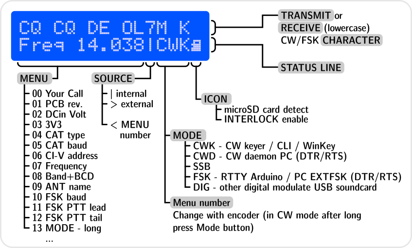
- First line show
- TX signal in CW and FSK mode
- RX sniffing decode RTTY (lowercase) during keying from PC
- Second status line show
- MENU
- Source keying
- MODE
- microSD card icon, if insert or INTERLOCK PTT lock if enable by input
Modes
Modes are switch automaticaly by TRX CAT. Translate table between TRX and OpenInterface mode in firmware.
If CAT not available you can change with MODE button on front panel.
- |CWK - CW Keyer by K3NG
- WinKey/CLI emulation
- SOURCE: USB/Serial interface
- INPUTS: Paddle Interlock Encoder Set/Mem_buttons
- OUTPUTS: CW1/2 PTT1/2
- >CWD - CW Daemon
- Keyng from PC
- SOURCE: USB/Serial interface DTR/RTS
- INPUTS: DTR(CW) RTS(PTT)
- OUTPUTS: CW1 PTT1
- |SSB - SSB
- LSB USB AM FM
- SOURCE: Mic-audio
- INPUTS: FootSwitch RTS
- OUTPUTS: PTT1
- >FSK - PC FSK keying
- RTTY keying from EXTFSK with sniffing and decode signal (lowercase) by JI3BNB / OK1HRA
- SOURCE: USB/Serial interface, Memory0-2_button
- INPUTS: DTR RTS
- OUTPUTS: PTT1 FSK
- |FSK generator by JI3BNB
- generator from Serial ASCII
- SOURCE: USB/Serial interface
- INPUTS: ASCII, Memory0-2_button
- OUTPUTS: PTT1 FSK
- |DIG - Audio FSK
- AFSK PSK and any modes modulate fom audio
- SOURCE: USB souncard
- INPUTS: RTS(PTT)
- OUTPUTS: PTT
Add-on
IP switch
Open Interface II can cooperate with IP Switch with ESP32-GATEWAY via four banks
- BankA controlled from first line ACC keyboard
first eight outputs on IP switch with ID 0-7 (show on LCD menu 18) - BankB controlled from second line ACC keyboard
last eight outputs on same IP switch (show on LCD menu 19) - BankC controlled from left rotary encoder
all sixteen outputs on IP switch with ID 8-F (activate and show on LCD menu 20) - BankD controlled from internal band decoder - not implemented yet
For working needed:
- Add not soldered parts C89 C90 R53 R55 R56 R57 to Open Interface PCB
- More continue on separete page ACC keyboard
Pinouts
RADIO 25 pin D-SUB
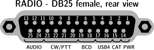
| pin-1 | in | Input power 8-18V DC from Transceiver |
| pin-2 | out | CAT TXD / CI-V |
| pin-3 | out | USB4 +5V output |
| pin-4 | - | USB4 -Data |
| pin-5 | out | BCD4 output TTL |
| pin-6 | out | BCD2 output TTL |
| pin-7 | out | PA PTT |
| pin-8 | out | PTT1 |
| pin-9 | out | CW1 |
| pin-10 | out | FSK |
| pin-11 | out | Microphone (TX) |
| pin-12 | out | TX audio |
| pin-13 | in | RX audio |
| pin-14 | - | Transceiver GND |
| pin-15 | in | CAT RXD |
| pin-16 | - | USB4 +Data |
| pin-17 | - | Transceiver GND |
| pin-18 | out | BCD3 output TTL |
| pin-19 | out | BCD1 output TTL |
| pin-20 | out | PTT2 |
| pin-21 | out | CW2 |
| pin-22 | out | PTT Microphone |
| pin-23 | in | Interlock |
| pin-24 | - | TX audio GND |
| pin-25 | - | RX audio GND |
| shield | - | Transceiver GND |
Microphone
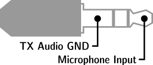
- 3,5 mm Jack - need preset internal jumper dependency to type your microphone
- JP7 - DC to MIC - allows DC voltage from TRX to your microphone
- OPEN for dynamic microphone
- SHORT for elecret microphone
Paddle

- 3,5 mm Jack - activate grounding input
- Settings Dot / Dash side available from
- Firmware
- Command mode after press SET button
Accessory connector (HDMI)
By default covered by break-out panel, because outputs are not protected.
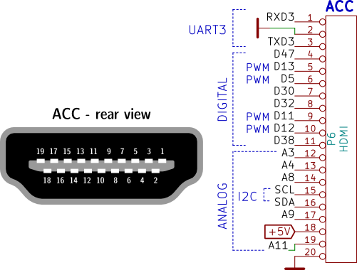
⚠
WARNING! - All ACC signals directly connect to ATMEGA chip without some ESD protection. Before use strongly recomended protect this lines. Otherwise, you can damage ATmega chip.
| used in device | |||
| ACC-1 | RXD | Serial3 | GPS-TXD |
| ACC-2 | GND | ACC keyboard/GPS-GND | |
| ACC-3 | TXD | Serial3 | GPS-RXD |
| ACC-4 | D47 | ACC keyboard-IN-LATCH | |
| ACC-5 | D13 | PWM | ACC keyboard-IN-DATA |
| ACC-6 | D5 | PWM | ACC keyboard-IN-CLOCK |
| ACC-7 | D30 | ACC keyboard-OUT-LATCH | |
| ACC-8 | D32 | One-Wire (planned) | |
| ACC-9 | D11 | PWM | ACC keyboard-OUT-DATA |
| ACC-10 | D12 | PWM | ACC keyboard-OUT-CLOCK |
| ACC-11 | D38 | ||
| ACC-12 | A2 | ||
| ACC-13 | A3 | ||
| ACC-14 | A8 | ||
| ACC-15 | SCL | I2C (Interrupt 2) | ACC keyboard-Interrupt |
| ACC-16 | SDA | I2C (Interrupt 3) | GPS-1PPS |
| ACC-17 | A9 | ||
| ACC-18 | +5V | ACC keyboard/GPS-PWR | |
| ACC-19 | A11 | ||
| ACC-20 | GND |
ATMEGA-2560 pinout (rev 3.1415)
| Arduino pins | connect to | in/out | Note |
| RX0 | USB | in | Connect to USB/serial interface |
| TX0 | USB | out | use for command CW keyer or firmware upload |
| D2 | Interlock | in | pull-up external, Interrupt 0 |
| D3 | PTT-232 | in | pull-up external, Interrupt 1 |
| D4 | CW tone | out | |
| D5 | ACC pin6 | PWM | |
| D6 | LCD-D4 | out | |
| D7 | LCD-D5 | out | |
| D8 | LCD-D6 | out | |
| D9 | LCD-D7 | out | |
| D10 | Ethernet SCS | out | |
| D11 | ACC pin9 | PWM | |
| D12 | ACC pin10 | PWM | |
| D13 | ACC pin5 | PWM | |
| TX3 | ACC pin3 | out | + Internal pins |
| RX3 | ACC pin1 | in | + Internal pins |
| TX2 | CAT | out | Connected in parallel to USB/serial CAT interface |
| RX2 | CAT | in | use for CAT sniffing or TX request |
| D18 | Encoder-B | in | pull-up internal (optional external*), Interrupt 5 (TX1) |
| D19 | PTT foot | in | pull-up external, Interrupt 4 (RX1) |
| D20 | SDA - ACC pin16 | in/out | I2C, Interrupt 3 |
| D21 | SCL - ACC pin15 | out | I2C, Interrupt 2 |
| D22 | PTT2 | out | |
| D23 | FSK | out | keying from arduino |
| D24 | Encoder-A | in | pull-up internal (optional external*) |
| D25 | PTT3 | out | |
| D26 | paddle Left | in | pull-up external |
| D27 | WinKey | out | HIGH if CW keying running (disable DTR/RTS) |
| D28 | paddle Right | in | pull-up external |
| D29 | AFSK | out | HIGH if AFSK keying (switch TX audio path) |
| D30 | ACC pin7 | ||
| D31 | PTT-PA | out | |
| D32 | ACC pin8 | ||
| D33 | FSK detector | in | pull-up external |
| D34 | CW1 | out | |
| D35 | CW2 | out | |
| D36 | MENU | in | pull-up external |
| D37 | LCD-E | out | |
| D38 | ACC pin11 | ||
| D39 | self reset | out | HIGH (enable with jumper JP5) |
| D40 | Sequencer | out | |
| D41 | PTT1 | out | |
| D42 | BCD1 | out | TTL Band data |
| D43 | BCD2 | out | TTL Band data |
| D44 | BCD3 | out | TTL Band data |
| D45 | BCD4 | out | TTL Band data |
| D46 | Ethernet detect | in | pull-up internal |
| D47 | ACC pin4 | ||
| D48 | Internal SMT pad | Free | |
| D49 | Internal SMT pad | Free | |
| D50 | MISO | out | |
| D51 | MOSI | out | |
| D52 | SCK | out | |
| D53 | microSD CS | out | |
| A0 | Internal SMT pad | Free | |
| A1 | CW keyer Memory button | in | pull-up external |
| A2 | LCD-RS | out | |
| A3 | ACC pin12 | ||
| A4 | ACC pin13 | ||
| A5 | microSD plug | in | pull-up internal |
| A6 | measure 3.3V | in | |
| A7 | measure input voltage | in | coefficient 11 |
| A8 | ACC pin14 | ||
| A9 | ACC pin17 | ||
| A10 | - | Free | |
| A11 | ACC pin19 | ||
| A12 | - | Free | |
| A13 | - | Free | |
| A14 | - | Free | |
| A15 | - | Free |
- If RC circuits installed