IP Switch with ESP32-GATEWAY
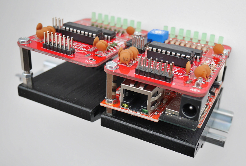
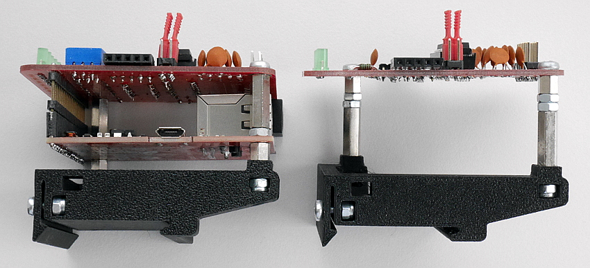
Designed for mounting to DIN rail.
Board serve as relay driver depenancy to used open collector/emmiter output chip. This kit worked with ESP32-GATEWAY Ethernet/WiFi module from OLIMEX. Below step by step assembled manual for 16 outputs (two boards), may be expandable.
Hardware
DC power jack

- ⚠ 5 volt DC only - higher voltage damage both electronics!
- Size 2,1/5,5mm diameter to connect input power 5V DC (center positive)
- Consumption below 500mA
P3 output header

| pin-1 | in | DC power supply +5V |
| pin-2 | in | DC power supply +5V |
| pin-3 | in | GND |
| pin-4 | in | GND |
| pin-5 | out | output 1 |
| pin-6 | out | output 2 |
| pin-7 | out | output 3 |
| pin-8 | out | output 4 |
| pin-9 | out | output 5 |
| pin-10 | out | output 6 |
| pin-11 | out | output 7 |
| pin-12 | out | output 8 |
| pin-13 | in | Vin, if use UDN driver |
| pin-14 | in | Vin, if use UDN driver |
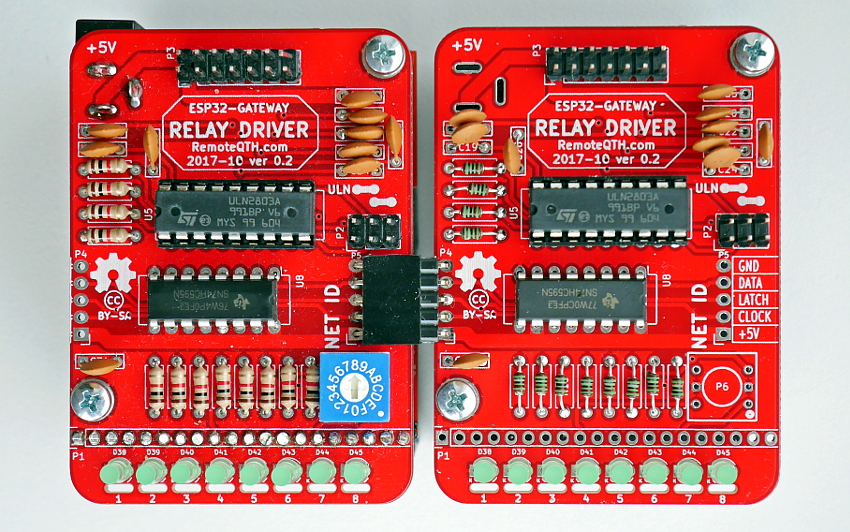
How to assembly
Top side PCB
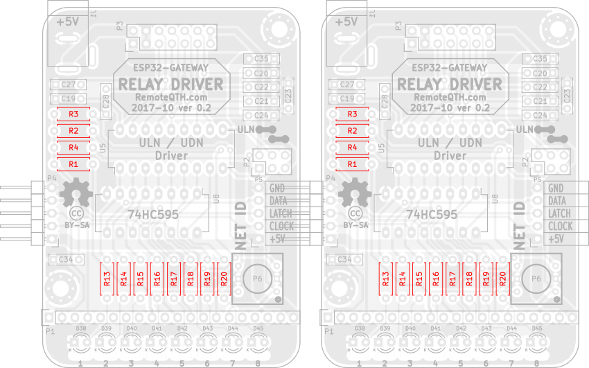
❏ Solder 2x12 1k rezistors R1-R14
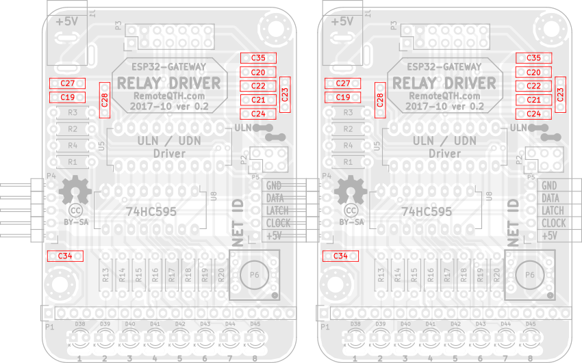
❏ 2x10 100n capacitors C19-C35
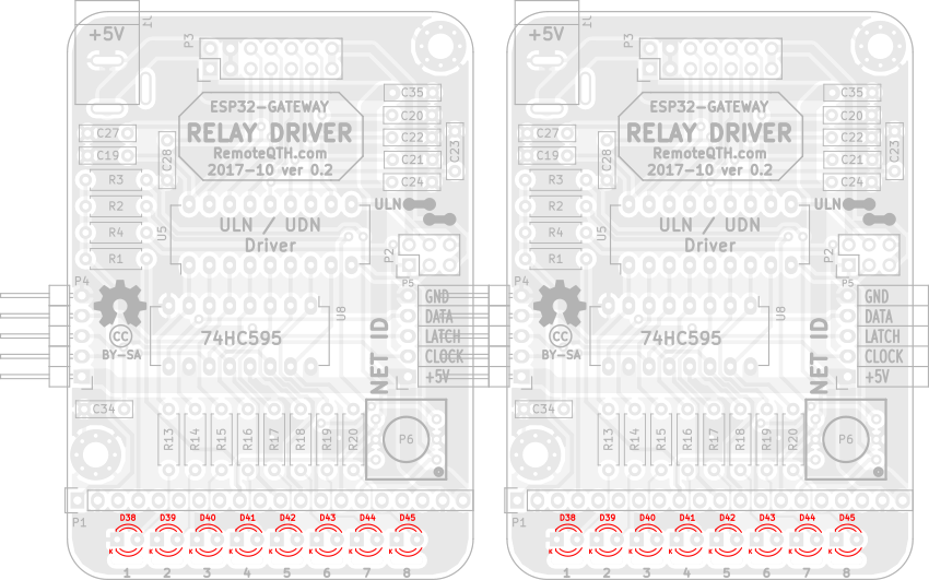
❏ 2x8 LED diodes D38-D45
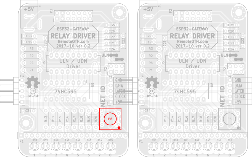
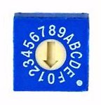
❏ One BCD ID switch P6 on LEFT board
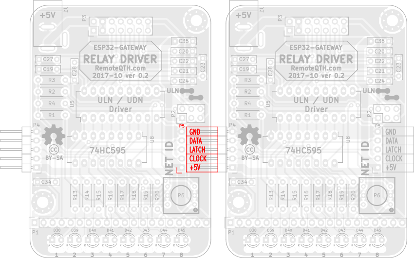
❏ One female pin header P5 on LEFT board
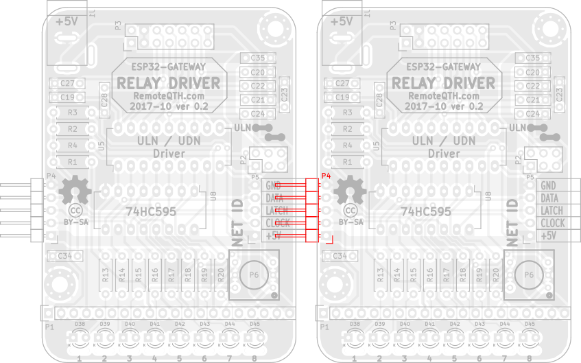
❏ One male pin header P4 on RIGHT board
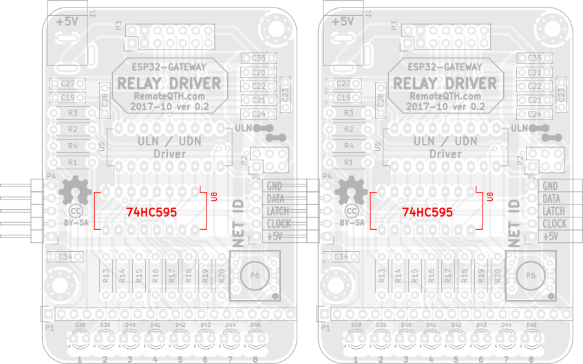
❏ 2x 74HC595 IO U8
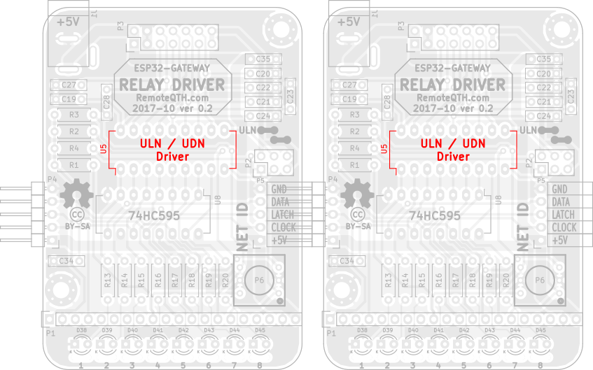
❏ 2x DIP socket for U5
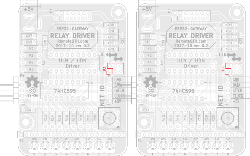
❏ 2x male 2x3 pin header P2
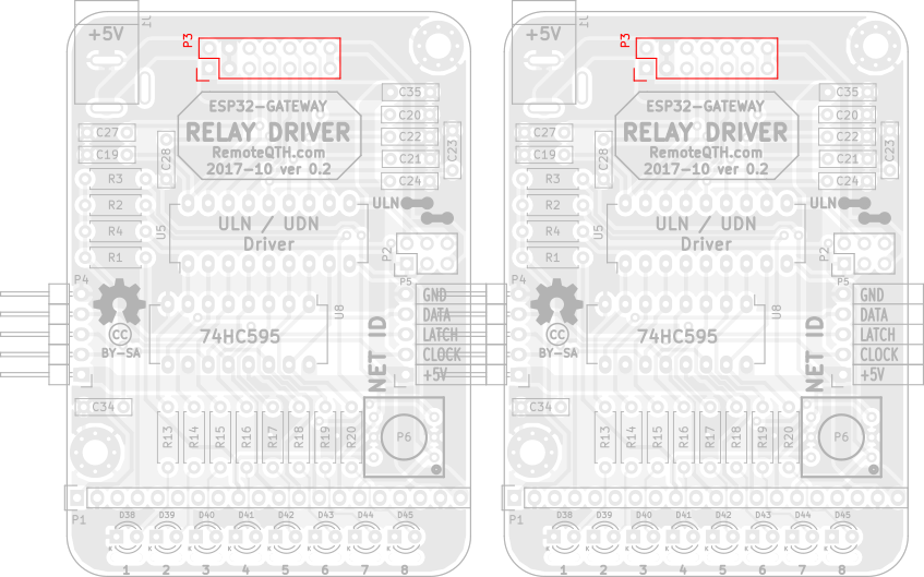
❏ 2x male 2x7 pin header P3
Bottom side PCB
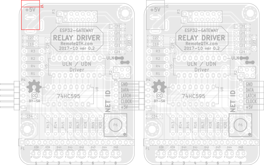
❏ One DC jack J1 on LEFT board
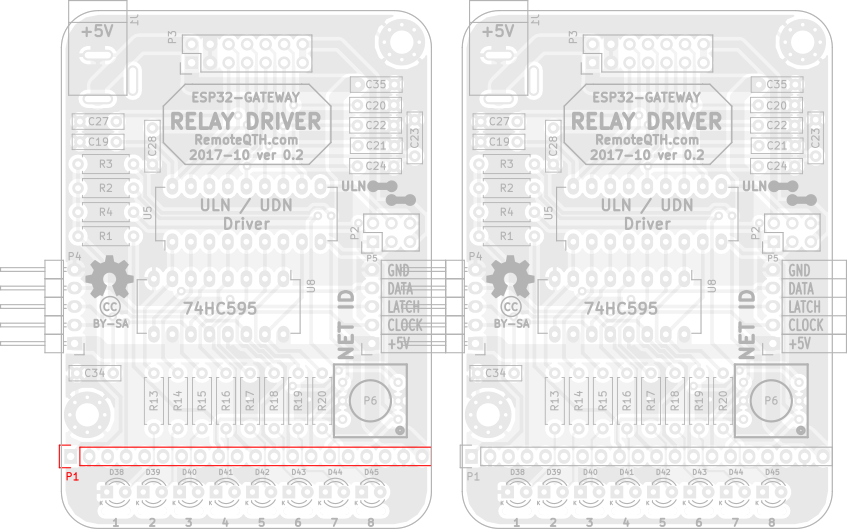
❏ One male 1x20 pin header P1 on LEFT board
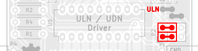
Output driver
❏ Put output driver to DIP socket by your preferency

- ULN chip for switching by output collector (grounding) need use two Jumpers on left P2 pin strip
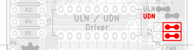
- UDN chip for switching by output emitter (voltage from P3 Vin) need use two Jumpers on right P2 pin strip
ESP32-GATEWAY board
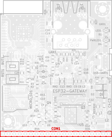
❏ One femmale 1x20 pin header CON1 on TOP side OLIMEX ESP32-GATEWAY
LED1 on ESP32-GATEWAY show
- three times flashes - receive IP from DHCP server - Ethernet
- two times flashes - receive IP from DHCP server - Wifi
- one time flashes - receive broadcast pair packet
How to mout to DIN rail
Firmware
- Download and install last version Arduino IDE
- Download and install ESP32 support for arduino from GitHub - prefered via board manager.
- Download IP switch firmware source from GitHub
- Edit source
- For use Ethernet (prefered connection) wiring connection preset configuration
#define ETHERNET               // Enable ESP32 ethernet (DHCP IPv4)
//#define WIFI                  // Enable ESP32 WIFI (DHCP IPv4)
- For use WiFi connection use this settings
//#define ETHERNET               // Enable ESP32 ethernet (DHCP IPv4)
#define WIFI                  // Enable ESP32 WIFI (DHCP IPv4)
and set your SSID and password for accessconst char* ssid = "YOUR-SSID"; const char* password = "YOUR-PASSWORD";
- Select menu Tools/Board:"OLIMEX ESP32-GATEWAY"
- Connect micro USB between ESP32-GATEWAY and PC
- Select menu Tools/Port/YOUR-CONNECTED-PORT
- Upload firmware
Setup
Setup are available via CLI (command line interface).
How to access
- connect micro USB cable
- run terminal - for example Ctrl+Shift+M in Arduino IDE
- set baudrate to 115200 and No line ending.
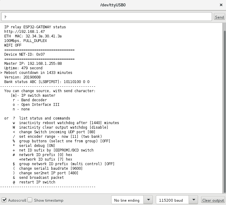
CLI contains some commands for set or show information.
Commands for set source device
- m - Manual IP switch
- r - Band decoder MK2
- o - Open Interface III
Other commands, RED is important
- ? - show status and help
- w - set inactivity time in minutes, after them IP switch will be restarted (watchdog)
- before reboot store current output setting and restore after start
- zero value disable this watchdog
- W - set inactivity time in minutes, after them IP switch will set all outputs to OFF
- if you need OFF all outputs after reboot watchdog, set smaller value than it
- zero value disable this watchdog
- / - set encoder range (2-g) for switching one from range
- % - enable/disable group buttons
- ! - SET group for each button separately
- : - List group buttons
- in one group may be activate only one output
- groups are free configurable
- the group can be any size 2-8 buttons
- there may be any buttons in the group, for example 1 and 8
- the number of groups is not limited
- * - enable/disable serial debugging
- + - select get Network ID sufix from eeprom or hardware BCD switch
- # - set network ID
- Prefix (four high bit) in hexadecimal format (0-f)
- in standart mode prefix expanded range of network ID
- if enable Multi control, prefix disable, and use only on master device for his idetifications
- Sufix (four low bit) in hexadecimal format (0-f)
- settings available if sufix get from eeprom
- in standart mode sufix use for identification
- in Multi control mode define group ID (id for all shared devices)
- $ - enable/disable Multi control function (sharing up to 16 master device)
- & - send broadcast packet for find control devices in local network
- . - if enable Multi control, show list detected IP switch by ID prefix
- @ - restart IP switch
For controlled from Manual IP switch
- Upload firmware by previous steps
- Set encoder range via CLI with command n
- Set source via CLI or web interface to m
- Set network ID prefix same on both devices via CLI in range 0-7
- Select Network ID sufix same on both devices with BCD switch in range ID 0-7
- Connect to same local network with DHCP as Manual IP switch
- After power up both devices, is automaticaly pair
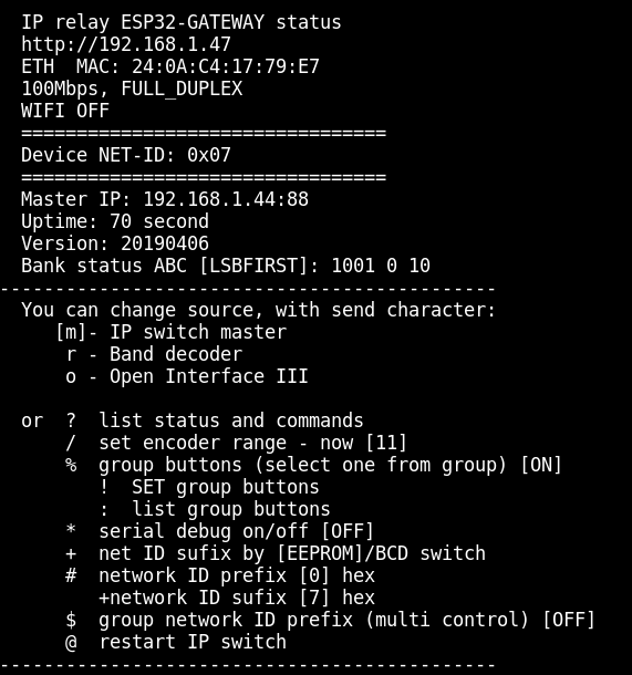
Web status page
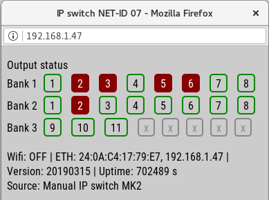
- Show all outputs status
- Parameter of WiFi or ethrnet IP connect
- Firmware version
- Device uptime
- How source controled his
- Notice - show this page can extend reaction latency IP switch
How IP addres got the device from the DHCP server?
- show in serial terminal after reboot, or send ? character
- or find some network scanner
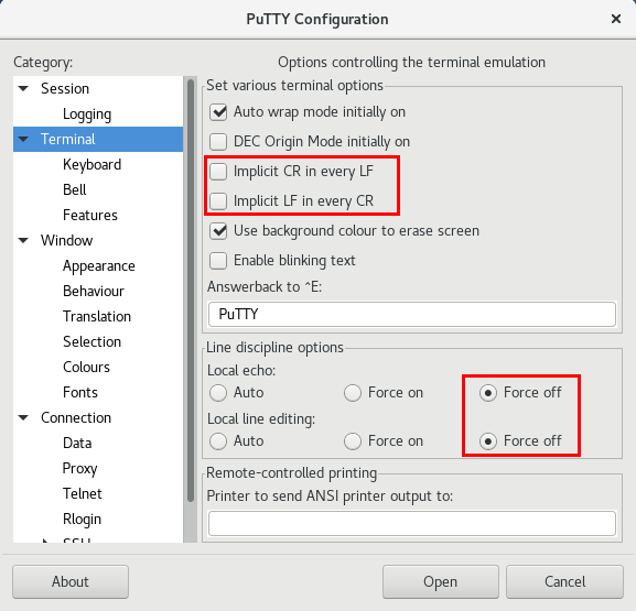
Telnet access with KEY
- Download and install PuTTY
- In menu Terminal preset CR/LF and line discipline by picture
- In main menu Session select or set the following values
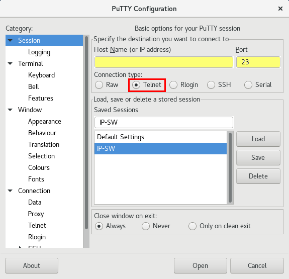
- select Telnet
- port 23
- write IP address
- Sessions may be saved for next time
- for connect press Open
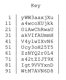
- Login confirm with press y
- Now answer four times the question of what character is on random selected position, in your key
- you either get the key together with the IP-switch, or paste it into the source code
const char* key="yWW3aaxjXua4wcoXUjkkOiAwChRwaUakVIfAUmmHV4ylwIXvN6Ucy3oH25T5ZzNYQ2r0L4s42tZIJT9XIgt9VVYxnDWtM7AVN6D8";
- if you enter wrong three times, login will be blocked for next ten minutes
- After login your IP address store to EEPROM and next key will be required only if change your IP address
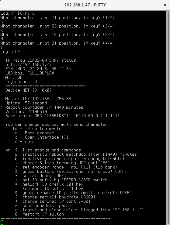
- for Logout press q
Secure remote manage
Configuration available via serial CLI (command line interface). This interface can be safely accessed to the Internet and encrypted connections to manage all features
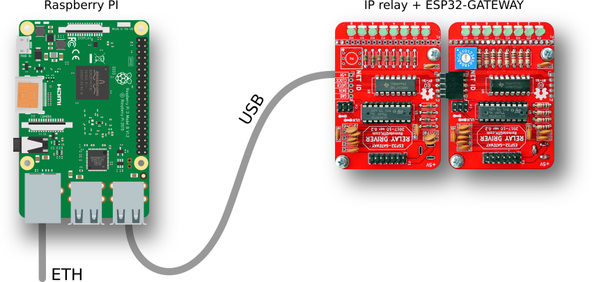
What you need
- any version Raspberry PI
- microSD card with Raspbian Lite
- micro USB cable
- 5V power adapter with micro usb cable
- ethernet connection
- for first start HDMI monitor and USB keyboard
How to start
- after first boot login to serial console with default login pi and password raspberry
- run command and enable SSH
sudo raspi-config
- run command and write down the shown IP address
ip a
- you can disconnect HDMI monitor and USB keyboard
- connect to Raspberry PI from any other PC
- update system with run command
sudo apt-get update && sudo apt-get upgrade
- install screen fith command
sudo apt-get install screen
- run screen
screen /dev/ttyUSB0 115200
- now after pres any key show status information and you can configure via CLI
- close screen with CTRL+A K and confirm y
- disconnect from Raspberry PI use command
exit