TX antenna - 2EL antenna array 4 direction
This revision is from 2018/06/09 15:41. You can Restore it.
This is TX-RX antenna mainly for lower bands. It is based on classic 4SQ with 90deg phase hybrid.
Quick Start Guide
- ⚠ NOTE: Input SWR of the hybrid is not SWR of the antenna!!!
Connector description
- There is standart RJ45 (ETHERNET) connector with shielding

- There is standart D-SUB 15 female connector with shielding

- Table

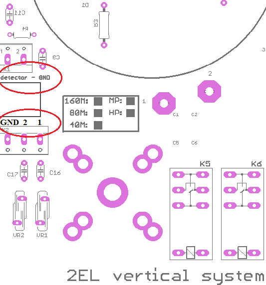
- Connectors on Hybrid PCB:
- detector = dummy load power
- 1 = DIR1 , 2 = DIR2

SWR LED bar settings
- ⚠ NOTE: Input SWR of the hybrid is not SWR of the antenna!!!
- SWR Range trimmer - Range of PWR in dummy load

Setting step by step
- Connect TRX (PA) to the 2EL hybrid - to Input port
- Connect Dummy load to the Dummy Load port ( you can insert PWR meter too )
- DO NOT connect any antenna element - leave it open
- Switch direction on controller to WEST or EAST
- Than when you TX (RTTY mode) all power goes to the dummy load port
- Open controller box
- There is SET SWR trimmer (blue one)
- With this trimmer you can set full range of LED bar for prefered MAX power in dummy load
⚠ NOTE: Do not forget thar SWR 2:1 on antenna elements is 1/10 of INPUT power to dummy load!! So for 1kW and SWR 2:1 is 100W in DL. There is no problem to have only a few Watts in DL when the antenna elements are right tuned!
- So set TRX power to your max PWR you want have in dummy load and set SET SWR trimmer to full LED bar range
- When LAST red LED is on, than PTT loop is disconnected * see jumpers setting
⚠ NOTE: When you set full scale for some PWR, for example 200W. Than you can go down with PWR from your TRX and you can see what PWR = LED COUNT. What is half of scale, first LED etc.
SWR ALARM settings
- When power in dummy load exceeds value you you set before, than protection circuit breaks PTT loop and Buzzer sound is ON.
- Jumpers:
- JP1 = ALARM - switch ON/OFF buzzer
- JP2 = LED BAR mode (dot/line)

- Return loss (RL) in dB to SWR:
ONLINE calculator RL to SWR

ToDo
- Cable wiring circuits