TX antenna - 2EL antenna array 4 direction
- Quick Start Guide
- Connector description
- Direction switching control:
- SWR LED bar settings
- Jumpers setting
- FEED lines length
- TUNNING ANT elements
This is TX-RX antenna mainly for lower bands. It is based on classic 4SQ with 90deg phase hybrid.
Quick Start Guide
- Connector description
- Direction control
- SWR LED bar settings How to set range of LED bar
- Jumpers setting LED bar mode, SWR PTT protection, supply voltage, direction LED...
- ANTENNA elements Ways to build antenna elements
- FEED lines length Calculation and examples of coax feed line length
- TUNNING ANT elements There is a few ways how to tune antenna
Connector description
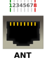
- There is standart RJ45 (ETHERNET) connector with shielding
- There is standart D-SUB 15 female connector with shielding
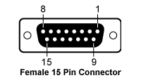
- Table
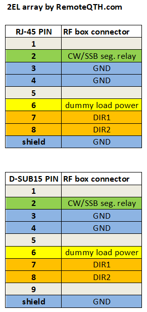
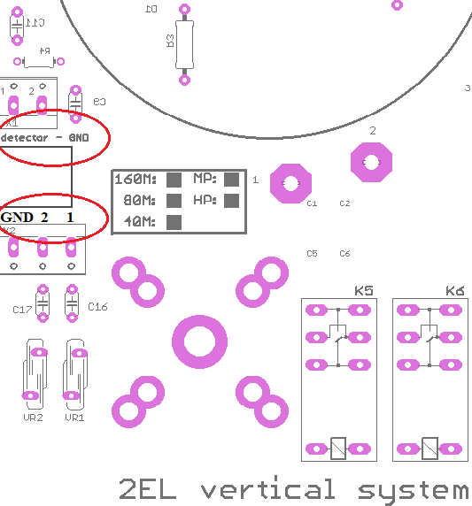
- Connectors on Hybrid PCB:
- detector = dummy load power (pin 6 on controller)
- 1 = DIR1 , 2 = DIR2
Direction switching control:
| DIRECTION | DIR1 | DIR2 |
| Controller | PIN 7 | PIN 8 |
| W | +12 V | - |
| N-S | - | - |
| E | +12 V | +12 V |
SWR LED bar settings
- ⚠ NOTE: Input SWR of the hybrid is not SWR of the antenna in W-E directions!!!
- ⚠ NOTE: For N-S direction, there is no power to Dummy load. Input SWR follows SWR of antennas!
SWR Range trimmer - Range of PWR in dummy load
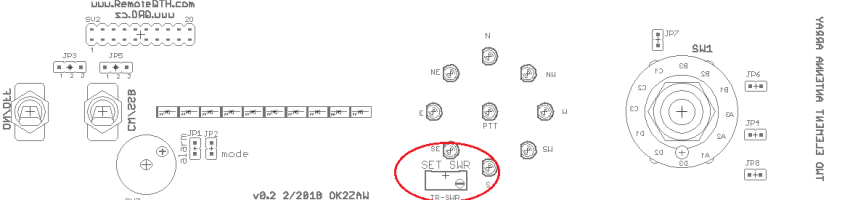
Setting step by step
- Connect TRX (PA) to the 2EL hybrid - to Input port
- Connect Dummy load to the Dummy Load port ( you can insert PWR meter too )
- DO NOT connect any antenna element - leave it open
- Switch direction on controller to WEST or EAST
- Than when you TX (RTTY mode) all power goes to the dummy load port
- Open controller box
- There is SET SWR trimmer (blue one)
- With this trimmer you can set full range of LED bar for prefered MAX power in dummy load
⚠ NOTE: Do not forget thar SWR 2:1 on antenna elements is 1/10 of INPUT power to dummy load!! So for 1kW and SWR 2:1 is 100W in DL. There is no problem to have only a few Watts in DL when the antenna elements are right tuned!
- So set TRX power to your max PWR you want have in dummy load and set SET SWR trimmer to full LED bar range
- When LAST red LED is on, than PTT loop is disconnected * see jumpers setting
⚠ NOTE: When you set full scale for some PWR, for example 200W. Than you can go down with PWR from your TRX and you can see what PWR = LED COUNT. What is half of scale, first LED etc.
Jumpers setting
- When power in dummy load exceeds value you you set before, than protection circuit breaks PTT loop and Buzzer sound is ON.
- Jumpers:
- JP1 = ALARM - switch ON/OFF buzzer and PTT LOOP break
- JP2 = LED BAR mode (dot/line)
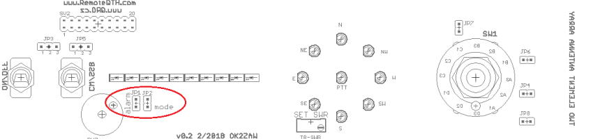
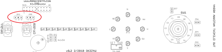
- JP3 = supply voltage for RF box relays - controller voltage or External
- JP5 = external CW/SSB segment relay - external antenna tunning: example
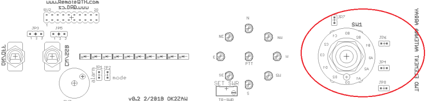
CHANGE LED INDICATION FOR THREE DIRECTIONS.
- JP4 = W N-S E
- JP6 = NW SW-NE SE
- JP7 = SW NW-SE NE
- JP8 = N W-E S
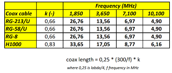
FEED lines length
- All ports on RF hybrid box are 50 Ohm. Antenna elements are connected to the box with 50 Ohm coax cables.
- The best way is to use Lambda/4 feed line lengths to take advantage of the current forcing properties of this length of line.
LENGTH IN METERs !!!
TUNNING ANT elements
⚠ NOTE: Input SWR of the hybrid is not SWR of the antenna for directions W ane E!!!
⚠ NOTE: Do not forget thar SWR 2:1 on antenna elements is 1/10 of INPUT power to dummy load (DL) for W and E directions!! So for 1kW and SWR 2:1 it is 100W in DL. There is no problem to have only a few Watts in DL when the antenna elements are right tuned!
There is a few ways how to do the right antenna elements tunning.
- With SWR LED bar indication *** for directions W or E ***
- Do *SWR LED bar settings at first
- TX with your TRX on RTTY (FSK) and tune TRX over the band
- You can see, where is the minimum power in dummy load = best SWR
- You can increase PWR (use PA) and find the minimum
- So if you set full scale of LED bar graf to 200W, and you TX with 2 KW into the antenna, you can see SWR 2:1 range
- With SWR meter on your TRX / SWR meter / VNA *** for direction N-S ***
- TX with your TRX on RTTY (FSK) and tune TRX over the band
- You can see, where is the minimum SWR on your TRX / SWR meter / VNA
- YTune around the band and find the minimum
- With 2-port VNA or Spectrum Analyser with TG *** For directions W or E ***
- Very nice way how to SEE antenna parameters is with VNA or SA
- Connect TX and RX port with short cable and do calibration
- Than connect TX port of VNA (TG on SA) to the IN port of hybrid
- RX port of VNA (IN of SA) connect to Dummy LOAD port on hybrid
- Connect all antenna elements
- Connect controller
- Now you cas see S21 parameters of antenna
- This will change with direction switching
- You can see the minimum of S21 what is the best SWR of antenna
- Frequency where there is that minimum, there is best SWR of antenna
- For example S21 = -20dB means 1/100 of Input power to dummy load
- On right tunned elements you can have more than -30dB ! what is 1W from 1kW !!!
- Return loss (RL) in dB to SWR:
ONLINE calculator RL to SWR

ToDo
- Cable wiring circuits