TX antenna - 4SQ-8DIR NEW 8 directions 4SQ antenna
This revision is from 2018/08/13 21:29. You can Restore it.
- Quick Start Guide
- Controller
- Connector description
- SWR LED bar settings
- TUNNING ANT elements
- Jumpers setting
This is TX-RX antenna mainly for lower bands. It is based on classic4SQ with 90deg phase hybrid. Construction is similar to K3LC design.
Very very nice document about classic 4SQ is from Franz DF6QV
Quick Start Guide
- Controller
- Connector description
- SWR LED bar settings How to set range of LED bar
- TUNNING ANT elements There is a few wais how to tune antenna
- Jumpers setting LED bar mode, SWR PTT protection


Controller

- 1 - DIRECTION SWITCH
- 2 - LED DIODE DIRECTION INDICATOR
- 3 - SWR LED BAR
- 4 - REMOTE ANTENNA SEGMENT RELAY SWITCH
- 5 - ON / OFF

- 1 - GND SCREW
- 2 - OPTIONAL: INTERNAL 230V POWER SUPPLY
- 3 - PTT LOOP: PTT IN FROM TRX (HOT SWITCH PROTECTION), PTT OUT TO PA (HIGH SWR PROTECTION)
- 4 - ACC TO RF BOX
- 5 - ACC TO RF BOX
- 6 - EXTERNAL POWER SUPPLY 12-15V / 1A
Connector description
Connectors on the Controller:
- There is standart RJ45 (ETHERNET) connector with shielding

- There is standart D-SUB 15 female connector with shielding

- Table

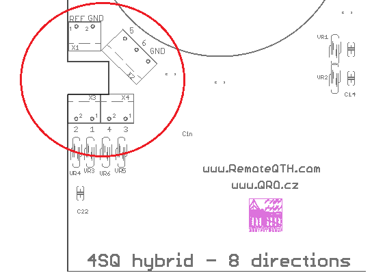
Connectors on the RF Hybrid PCB:
- REF = dummy load power
- 1 to 6 = K1 to K6
SWR LED bar settings
- LINE mode

- DOT mode

- ⚠ NOTE: Input SWR of the hybrid is not SWR of the antenna!!!
Trimmer and Jumpers on the Front Panel of controller
- You need to open the controller box
- SWR Range trimmer - Range of PWR in dummy load
- JP1 - ALARM - When the SWR is full scale of the LED bar, than buzzer sound is ON and PTT loop is broken.
- JP2 - LED bar MODE - LINE or DOT as 2 pictures above

Setting step by step
- Connect TRX (PA) to the 4SQ-8DIR hybrid - to Input port
- Connect Dummy load to the Dummy Load port ( you can insert PWR meter too )
- DO NOT connect any antenna element - leave it open
- Than when you TX (RTTY mode) all power goes to the dummy load port
- Connect controller box and open it
- There is SET SWR trimmer (blue one)
- With this trimmer you can set full range of LED bar for prefered MAX power in dummy load

⚠ NOTE: Do not forget thar SWR 2:1 on antenna elements is 1/10 of INPUT power to dummy load!! So for 1kW and SWR 2:1 is 100W in DL. There is no problem to have only a few Watts in DL when the antenna elements are right tuned!
- So set TRX power to your max PWR you want have in dummy load and set SET SWR trimmer to full LED bar range
- When LAST red LED is on, than PTT loop is disconnected * see jumpers setting
⚠ NOTE: When you set full scale for some PWR, for example 200W. Than you can go down with PWR from your TRX and you can see what PWR = LED COUNT. What is half of scale, first LED etc.
TUNNING ANT elements
⚠ NOTE: Input SWR of the hybrid is not SWR of the antenna!!!
⚠ NOTE: If you do not connect any ANT into all 4 ports, SWR on you TRX is very close to 1:1 but ALL power is going to dummy load = ANT SWR is ∞:1!!!
⚠ NOTE: Do not forget thar SWR 2:1 on antenna elements is 1/10 of INPUT power to dummy load (DL)!! So for 1kW and SWR 2:1 it is 100W in DL. There is no problem to have only a few Watts in DL when the antenna elements are right tuned!
There is a few ways how to do the right antenna elements tunning.
- With SWR LED bar indication
- Do *SWR LED bar settings at first
- TX with your TRX on RTTY (FSK) and tune TRX over the band
- You can see, where is the minimum power in dummy load = best SWR
- You can increase PWR (use PA) and find the minimum
- So if you set full scale of LED bar graf to 200W, and you TX with 2 KW into the antenna, you can see SWR 2:1 range
- With 2-port VNA or Spectrum Analyser with TG
- Very nice way how to SEE antenna parameters is with VNA or SA
- Connect TX and RX port with short cable and do calibration
- Than connect TX port of VNA (TG on SA) to the IN port of hybrid
- RX port of VNA (IN of SA) connect to Dummy LOAD port on hybrid
- Connect all antenna elements
- Connect controller
- Now you cas see S21 parameters of antenna
- This will change with direction switching
- You can see the minimum of S21 what is the best SWR of antenna
- Frequency where there is that minimum, there is best SWR of antenna
- For example S21 = -20dB means 1/100 of Input power to dummy load
- On right tunned elements you can have more than -30dB ! what is 1W from 1kW !!!
- Return loss (RL) in dB to SWR:
ONLINE calculator RL to SWR

Jumpers setting
ToDo
- Coax info