TX antenna - 4SQ-8DIR NEW 8 directions 4SQ antenna
- Quick Start Guide
- FAQ
- Controller
- Antenna elements orientation
- Connector description
- SWR LED bar settings
- Trimmer and Jumpers on the Front Panel of controller
- Jumpers on connector board
- TUNNING ANT elements
- ToDo
This is TX-RX antenna mainly for lower bands. It is based on classic 4SQ with 90deg phase hybrid. Construction is similar to K3LC design.
Very very nice document about classic 4SQ is from Franz DF6QV
Quick Start Guide
- Frequently Asked Questions
- Controller
- Antenna elements example
- Antenna elements orientation
- Connector description
- SWR LED bar settings How to set range of LED bar
- Jumpers and trimmer settings
- TUNNING ANT elements There is a few wais how to tune antenna
- Jumpers setting LED bar mode, SWR PTT protection

FAQ
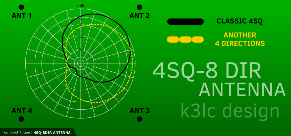
Phasing of Elements - How it works for 4 + 4 directions
The conventional antenna fire outward through the corners of the square formed by the four elements, while the modified array can also fire througheach of the four side s. In either case, all the elements are driven by the equalamplitude base currents, but the phase angles are differentresulting in beams heading in various directions.
When firing through sides of the square, there are two front elements and two rear elements. There the currents in the front elements lag those of the rear elements by 90°. More in nice article (source): K3LC design.
Element Spacing in a 4-Square
You do not have to use exactly 0,25 lambda. Please have a look at simulations: Franz DF6QV
System impedances - Elements + Transformation Lines
For a good match the four outputs of the system must be terminated with 100 Ohms. The radiators are connected to them via 75Ω-λ/4-lines transforming the 50 Ohm-feed-impedance of the radiators to the required 100 Ohms. If the feed-impedance of the radiator is different from 50 Ohms, it must be transformed to 50 ± j0 Ohms for an optimal match. The λ/4-lines should be made from coaxial cable with a velocity factor ≥ 0.7, otherwise a radiator distance of λ/4 cannot be obtained.
- For elevated radial elements you can obtain 50 Ohm feed impedance and use 75 Ohms coax for Transformation Lines
- For ground mounted elemets with great ground system the impedance is around 36 Ohms. There 60 Ohms coax cable should be used for Transformation Lines or tune impedance to 50 Ohms in feed point.
Transformation Line calculation lambda / 4
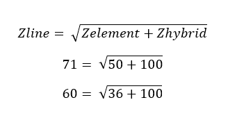
- This hybrid is designed for 100 Ohm from transformation line.
- When you use 50 Ohms in feed point of vertical, than you should have 100 Ohms at the end of 75 Ohm TL.
- When you use 36 Ohms in feed points (ideal vertical on great ground system) you will have around 150 Ohms! What means that imput SWR of hybrid and dumped power will be higher!
Setup notes by Franz DF6QV
Put the box in the center of the planned 4-square and lay the phase lines out in the desired directions. Keep them at an angle of 90 degrees to each other. If using PE insulated lines the positions of the radiators are fixed by their ends, but then the spacing is not quite λ/4. With foam-insulated lines the positions of the radiators have to be chosen at a distance of 0,175 λ (0.25 λ / 1.41) from the center for a λ/4-spacing.
Before connecting the radiator to the transformation lines each radiator has to be checked for resonance on the operating frequency with a suitable analyzer. Important: all other radiators are not connected to their feed-lines!
After connecting the feed-lines you can measure the transformed feed-point impedance of the antenna at their ends in the center of the 4-square.It should be about 100 Ohms. Values between 90 and 110 Ohms are acceptable. To check the display on the remote control box, remove all λ/4-lines from the phasing-box; only the built-in dummy load is effective. As the output ports are open, the input power is totally reflected into the dummy load. You can check this by sending 100 watts. The instrument should then read about 0 dB. The SWR remains low in this test!
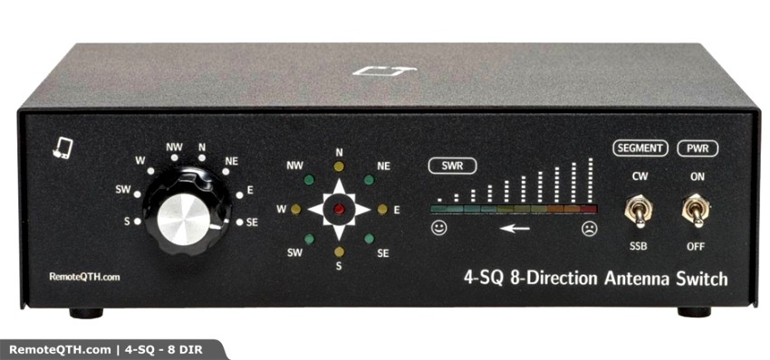
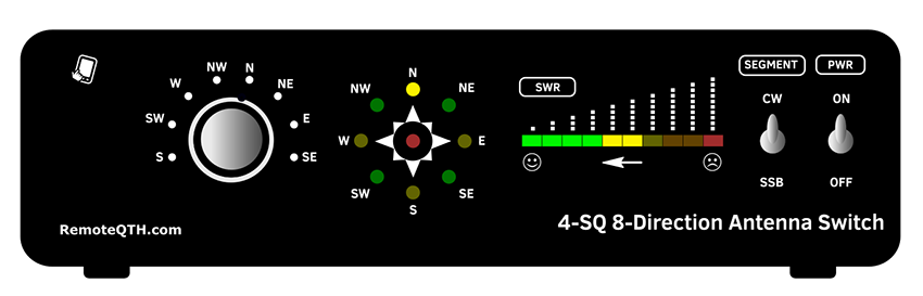
Controller
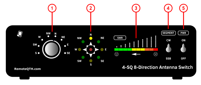
- 1 - DIRECTION SWITCH
- 2 - LED DIODE DIRECTION INDICATOR
- 3 - SWR LED BAR
- 4 - REMOTE ANTENNA SEGMENT RELAY SWITCH
- 5 - ON / OFF
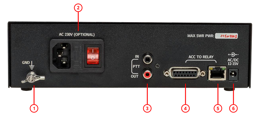
- 1 - GND SCREW
- 2 - OPTIONAL: INTERNAL 230V POWER SUPPLY
- 3 - PTT LOOP: PTT IN FROM TRX (HOT SWITCH PROTECTION), PTT OUT TO PA (HIGH SWR PROTECTION)
- 4 - ACC TO RF BOX
- 5 - ACC TO RF BOX
- 6 - EXTERNAL POWER SUPPLY 12-15V / 1A
Antenna elements orientation
- It is based on the classic 4SQ with 90deg phase hybrid.
- Construction is similar to K3LC design
- bigger picture

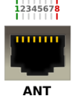
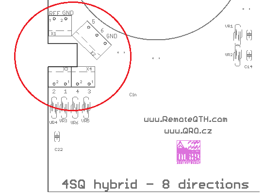
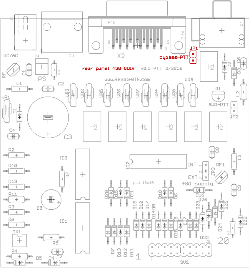
Connector description
Connectors on the Controller:
- There is standart RJ45 (ETHERNET) connector with shielding
- There is standart D-SUB 15 female connector with shielding
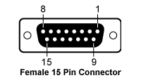
Table
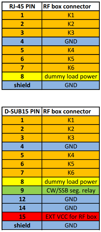
Connectors on the RF Hybrid PCB:
- REF = dummy load power
- 1 to 6 = K1 to K6
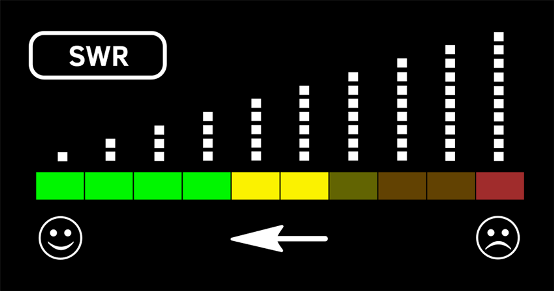
SWR LED bar settings
- LINE mode
- DOT mode
- ⚠ NOTE: Input SWR of the hybrid is not SWR of the antenna!!!
Trimmer and Jumpers on the Front Panel of controller
- You need to open the controller box
- JP1 - ALARM - When the SWR is full scale of the LED bar, than buzzer sound is ON and PTT loop is broken.
- JP2 - LED bar MODE - LINE or DOT as 2 pictures above
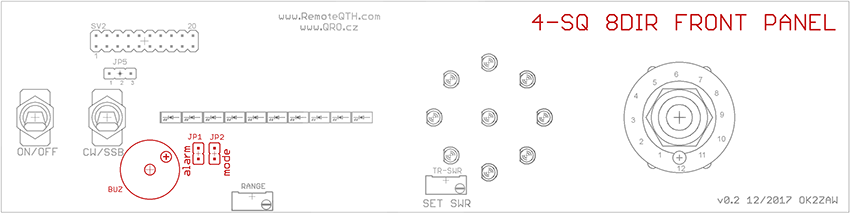
- SWR Range trimmer - Range of PWR in dummy load
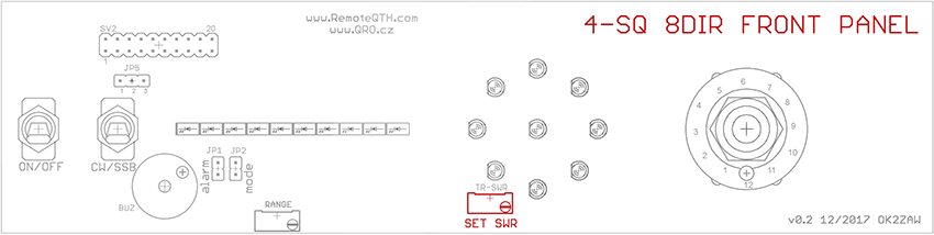
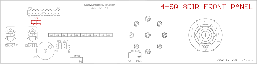
- JP5 - EXTERNAL ANTENNA SEGMENT RELAY
- JP5 CONNECTED 1+2 = +12V IN SSB POSITION (on PIN9 on ACC connector)
- JP5 CONNECTED 2+3 = +12V IN CW POSITION (on PIN9 on ACC connector)
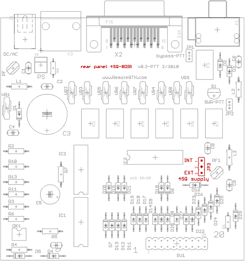
Jumpers on connector board
- JP1 - ByPass PTT loop - alarm is OFF for PTT - When the SWR is full scale of the LED bar, than buzzer sound is ON and PTT loop is broken.
- JP2 - OPEN = When the SWR is full scale of the LED bar, than buzzer sound is ON and PTT loop is NOT broken.

- JP3 - Voltage supply for RF hybrid. You can use supply from controller or External one - see Connector info - PIN 15. Internal = 1+2, external = 2+3 short on JP3.
Setting step by step
- Connect TRX (PA) to the 4SQ-8DIR hybrid - to Input port
- Connect Dummy load to the Dummy Load port ( you can insert PWR meter too )
- DO NOT connect any antenna element - leave it open
- Than when you TX (RTTY mode) all power goes to the dummy load port
- Connect controller box and open it
- There is SET SWR trimmer (blue one)
- With this trimmer you can set full range of LED bar for prefered MAX power in dummy load
⚠ NOTE: Do not forget thar SWR 2:1 on antenna elements is 1/10 of INPUT power to dummy load!! So for 1kW and SWR 2:1 is 100W in DL. There is no problem to have only a few Watts in DL when the antenna elements are right tuned!
- So set TRX power to your max PWR you want have in dummy load and set SET SWR trimmer to full LED bar range
- When LAST red LED is on, than PTT loop is disconnected * see jumpers setting
⚠ NOTE: When you set full scale for some PWR, for example 200W. Than you can go down with PWR from your TRX and you can see what PWR = LED COUNT. What is half of scale, first LED etc.
TUNNING ANT elements
⚠ NOTE: Input SWR of the hybrid is not SWR of the antenna!!!
⚠ NOTE: If you do not connect any ANT into all 4 ports, SWR on you TRX is very close to 1:1 but ALL power is going to dummy load = ANT SWR is ∞:1!!!
⚠ NOTE: Do not forget thar SWR 2:1 on antenna elements is 1/10 of INPUT power to dummy load (DL)!! So for 1kW and SWR 2:1 it is 100W in DL. There is no problem to have only a few Watts in DL when the antenna elements are right tuned!
There is a few ways how to do the right antenna elements tunning.
- three of tham:
With SWR LED bar indication
- Do *SWR LED bar settings at first
- TX with your TRX on RTTY (FSK) and tune TRX frequency over the band
- You can see, where is the minimum power in dummy load = best SWR
- You can increase PWR (use PA) and find the minimum
- So if you set full scale of LED bar graf to 200W, and you TX with 2 KW into the antenna, you can see SWR 2:1 range
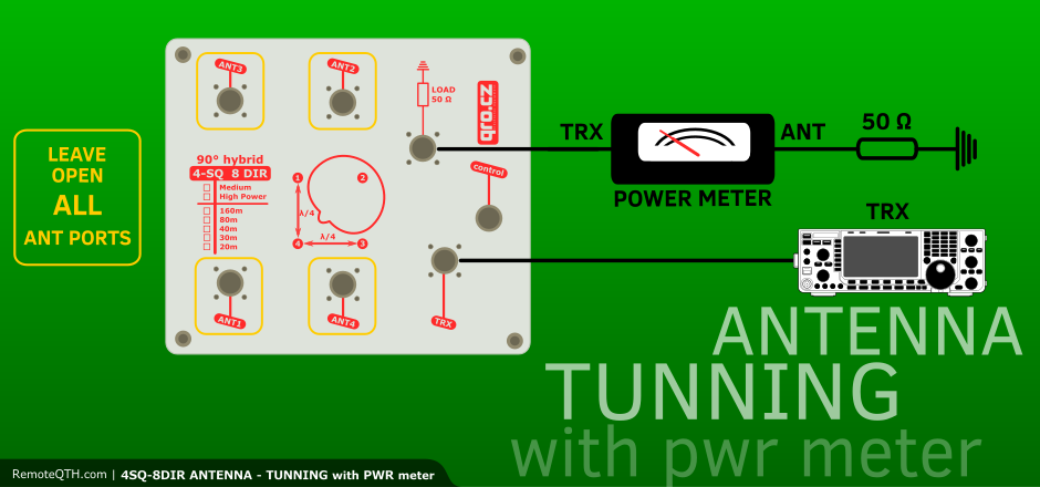
With PWR meter
- Connect PWR meter between RF hybrid and dummy load
- TX with your TRX on RTTY (FSK) and tune TRX frequency over the band
- You can see, where is the minimum power in dummy load = best SWR
- You can increase PWR (use PA) and find the minimum
- 1/10 of the input power in the dummy load (shown on your PWR meter) means SWR 2:1

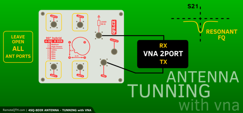
With 2-port VNA or Spectrum Analyser with TG
- Very nice way how to SEE antenna parameters is with VNA or SA
- Connect TX and RX port with short cable and do calibration
- Than connect TX port of VNA (TG on SA) to the IN port of hybrid
- RX port of VNA (IN of SA) connect to Dummy LOAD port on hybrid
- Connect all antenna elements
- Connect controller
- Now you cas see S21 parameters of antenna
- This will change with direction switching
- You can see the minimum of S21 what is the best SWR of antenna
- Frequency where there is that minimum, there is best SWR of antenna
- For example S21 = -20dB means 1/100 of Input power to dummy load
- On right tunned elements you can have more than -30dB ! what is 1W from 1kW !!!
- bigger picture
- Return loss (RL) in dB to SWR:
ONLINE calculator RL to SWR

ToDo
- Coax info
Rev. 0.2 last update May 2019