Manual IP switch II
This revision is from 2019/01/24 21:53. You can Restore it.
← Old web page | Previous MK1 version
Manual IP switch MK2 is delivered with two parts - IP relay diver KIT (needs to assemble) and assembled IP control. Both parts have firmware installed and automaticaly pair in local network with available DHCP server.
Quick start guide in two step
- IP Switch relay driver KIT
- Assembly KIT by this instructions.
- Connect ethernet to local LAN with available DHCP server
- Connect 5V power DC adapter
- Set NET-ID-sufix with BCD switch in the range 0-7, for example 0.
- IP control
- This part is assembled and tested.
- Connect ethernet to local LAN with available DHCP server
- Set NET-ID-sufix with bottom side BCD switch in the range 0-7, the number must be the same as on IP-switch relay driver.
- Connect micro USB cable for power supply.
- Wait to pair and start to use.
The hardware
- IP Switch relay driver KIT is on its own page.
- IP control
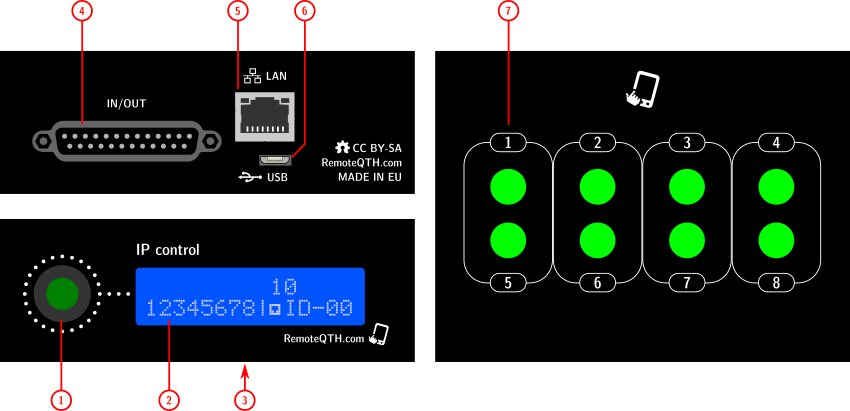
- 1 - rotary Encoder switch one from 2-16 outputs
- 2 - status LCD display

- Points in the first row indicate the scope of the encoder.
- 3 - NET-ID BCD, switch sufix in range 0-7

- 4 - 25 pin D-SUB (inputs outputs not use)
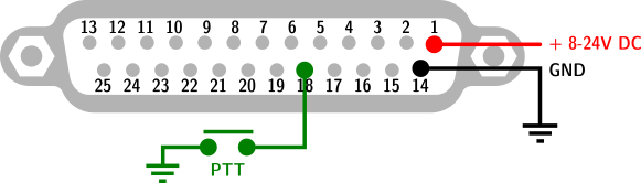
- PIN-1 DC power, typicaly 13,8V from transceiver
- PIN-18 PTT input
- PIN-14 GND
- 5 - Ethernet
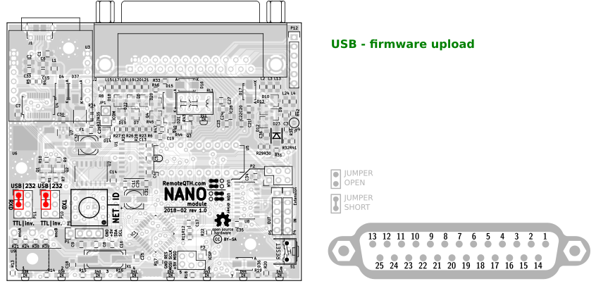
- 6 - micro USB for upload firmware or power
- 7 - eight light button - light after receive confirming from remote relay
Circuits
- Based on universal NANO module
- And expanding light keypad
Pinouts 25 pin D-SUB
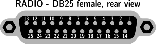
| pin-1 | in | Input power 8-18V DC from Transceiver |
| pin-2 | in | ICOM CI-V |
| pin-3 | out | TXD TTL |
| pin-4 | out | TXD TTL inverted |
| pin-5 | out | TXD 232 level |
| pin-6 | out | PTT output |
| pin-7 | out | Relay 2 |
| pin-8 | out | Relay 4 |
| pin-9 | out | Relay 6 |
| pin-10 | out | Relay 8 |
| pin-11 | in/out | BCD4 |
| pin-12 | in/out | BCD2 |
| pin-13 | in | AZ |
| pin-14 | - | GND |
| pin-15 | in | RXD TTL |
| pin-16 | in | RXD TTL inverted |
| pin-17 | in | RXD 232 level |
| pin-18 | in | PTT in |
| pin-19 | out | Relay 1 |
| pin-20 | out | Relay 3 |
| pin-21 | out | Relay 5 |
| pin-22 | out | Relay 7 |
| pin-23 | out | +5V |
| pin-24 | in/out | BCD3 |
| pin-25 | in/out | BCD1 |
| shield | - | GND |
Firmware
- Download and install Arduino IDE 1.8.3 od older
- Install library
- Wire
- LiquidCrystal_I2C or LiquidCrystal_PCF8574
- Download Band Decoder 2 firmware source from GitHub
- Preset two jumper in P10/P11 pin geader
- Connect micro USB cable between band decoder and PC
- Configure... (more in the chapter Configure TRX inputs)
- Select menu Tools/Board:"Arduino Nano"
- Select menu Tools/Port/YOUR-CONNECTED-PORT
- Upload firmware
LCD display
❏ I2C display need preset address in firmware
#define LcdI2Caddress 0x3F
The most common are values 0x27 or 0x3F.
- If display dont work
- Upload I2C scanner firmware
- Open terminal Ctrl+Shift+M
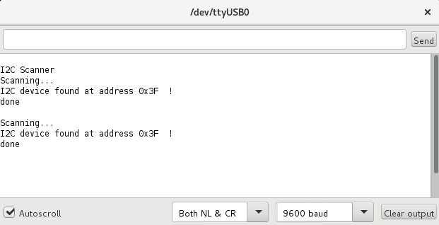
- Write detect addres to band decoder firmware
Select I2C LCD chip
- If type of chip is PCF8574AT
- Install library LiquidCrystal_I2C
- Disable line
// #define LCD_PCF8574T
- If type of chip is PCF8574T
- Install library LiquidCrystal_PCF8574
- Enable line
#define LCD_PCF8574T
❏ Preset LCD contrast with potentiometer on rear side LCD module
CONFIGURE OUTPUTS
You can uncomment more than one output, but not all combinations are worked.
Always usable - may all at once.
- 8 output driver - allways enabled
- Yaesu BCD - allways enabled except activate Yaesu BCD input
- Serial echo
Only one from (not available during active Frequency request option (available only one TXD line)
//=====[ Outputs ]============================================================================================
// #define SERIAL_echo        // Feedback on serial line in same baudrate, CVS format <[band],[freq]>\n
// #define ICOM_CIV_OUT       // send frequency to CIV ** you must set TRX CIV_ADRESS, and disable ICOM_CIV **
// #define KENWOOD_PC_OUT     // send frequency to RS232 CAT ** for operation must disable REQUEST **
// #define YAESU_CAT_OUT      // send frequency to RS232 CAT ** for operation must disable REQUEST **
8 output driver
- Allways enabled.
How to expand outputs
Band decoder use internal shift register with 8 outputs. This is free expandable. You can connect next shift register to P5 output connector. Schematics module for serial chain linkink on picture.
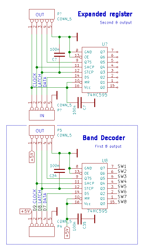
And sets number of all shift register in firmware
- internal = 1
- internal + one external =2
int NumberOfBoards = 2; // number of eight byte shift register 0-x
SERIAL ECHO
Activate uncomment line
#define SERIAL_echo
Requires setting
#define SERBAUD 9600
YAESU BCD output
Always activate - except enable BCD input.
You can set rules to select BCD output, dependency to detected band input.
//=====[ BCD OUT ]===========================================================================================

        const boolean BCDmatrixOUT[4][16] = { /*
        --------------------------------------------------------------------
        Band # to output relay   0   1   2   3   4   5   6   7   8   9  10
        (Yaesu BCD)                 160 80  40  30  20  17  15  12  10  6m
        --------------------------------------------------------------------
                                 |   |   |   |   |   |   |   |   |   |   |
                                 V   V   V   V   V   V   V   V   V   V   V
                            */ { 0,  1,  0,  1,  0,  1,  0,  1,  0,  1,  0, 1, 0, 1, 0, 1 }, /* --> DB25 Pin 11
                            */ { 0,  0,  1,  1,  0,  0,  1,  1,  0,  0,  1, 1, 0, 0, 1, 1 }, /* --> DB25 Pin 24
                            */ { 0,  0,  0,  0,  1,  1,  1,  1,  0,  0,  0, 0, 1, 1, 1, 1 }, /* --> DB25 Pin 12
                            */ { 0,  0,  0,  0,  0,  0,  0,  0,  1,  1,  1, 1, 1, 1, 1, 1 }, /* --> DB25 Pin 25
        */};

//============================================================================================================
ICOM CIV output
Activate uncomment line
#define ICOM_CIV_OUT
Requires baud rate and CIV address in setting section of source code
#define SERBAUD      9600    // [baud] Serial port in/out baudrate
#define CIV_ADR_OUT  0x56    // HEX Icom adress (0x is prefix)
- short JP1 left (TXD)
KENWOOD CAT output
Activate uncomment line
#define KENWOOD_PC_OUT
Requires baud rate in setting section of source code
#define SERBAUD 9600 // [baud] Serial port in/out baudrate
- short JP1 right (TXD)
- short JP7
YAESU CAT output
Activate uncomment line
#define YAESU_CAT_OUT
Requires baud rate in setting section of source code
#define SERBAUD 9600 // [baud] Serial port in/out baudrate
- short JP1 right (TXD)
- short JP7
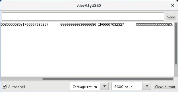
Debug mode
Allows read comunications and show in terminal
- Enable debug in firmware
#define DEBUG
- Enable inputs by connected radio
//=====[ Inputs ]=============================================================================================
// #define YAESU_BCD          // TTL BCD in A
// #define ICOM_ACC           // voltage 0-8V on pin4 ACC(2) connector - need calibrate table
// #define INPUT_SERIAL       // telnet ascii input - cvs format [band],[freq]\n
// #define ICOM_CIV           // read frequency from CIV
// #define KENWOOD_PC         // RS232 CAT
// #define YAESU_CAT          // RS232 CAT YAESU CAT since 2015 ascii format
// #define YAESU_CAT_OLD      // Old binary format RS232 CAT ** tested on FT-817 **
- Upload firmware
- Preset RXD P11 dependency to connected transceiver
- 232 for RS232 communications
- TTL for 5V level data
- Preset P10 to USB
- Open arduino terminal, and set same baudrate by firmware preset
#define SERBAUD 9600
- Sniffing communications (on picture Kenwood CAT)...