Manual IP switch II
This revision is from 2019/03/29 23:35. You can Restore it.
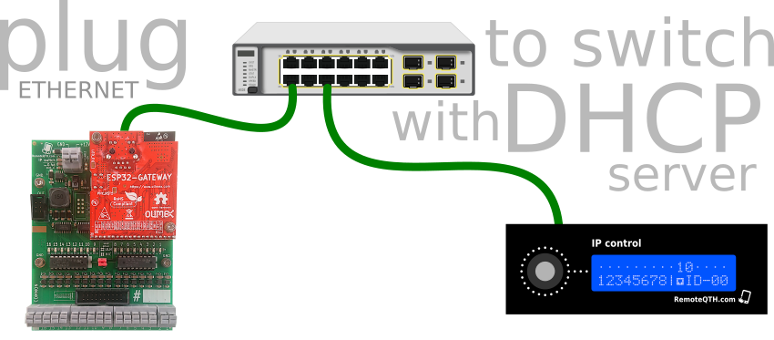
Manual IP switch MK2 is delivered with two parts - IP relay diver KIT (needs to assemble) and assembled IP control. Both parts have firmware installed and automaticaly pair in local network with available DHCP server.
Quick start guide in two step
Manual IP switch is consists of two parts
- IP Switch relay driver KIT
- Assembly KIT by this instructions.
- Connect ethernet to local LAN with available DHCP server
- Connect 5V power DC adapter - higher voltage damage both electronics!
- Set NET-ID-sufix with BCD switch in the range 0-7, for example 0.
- IP control
- This part is assembled and tested.
- Connect ethernet to local LAN with available DHCP server
- Set NET-ID-sufix with bottom side BCD switch in the range 0-7, the number must be the same as on IP-switch relay driver.
- Connect micro USB cable for power supply.
- Wait to pair and start to use.
The hardware
- IP Switch relay driver KIT is on its own page.
- IP control
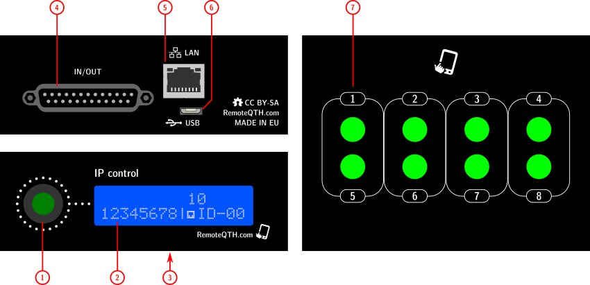
- 1 - rotary Encoder switch one from 2-16 outputs
- 2 - status LCD display

- Points in the first row indicate the scope of the encoder.
- 3 - NET-ID BCD, switch sufix in range 0-7

- 4 - 25 pin D-SUB (inputs outputs not use)
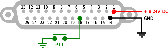
- PIN-1 DC power, typicaly 13,8V from transceiver
- PIN-18 PTT input
- PIN-14 GND
- 5 - Ethernet
- 6 - micro USB for upload firmware or power
- 7 - eight light button - light after receive confirming from remote relay
Circuits
- Based on universal NANO module
- And expanding light keypad
Pinouts 25 pin D-SUB
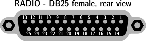
| pin-1 | in | Input power 8-18V DC from Transceiver |
| pin-2 | in | ICOM CI-V |
| pin-3 | out | TXD TTL |
| pin-4 | out | TXD TTL inverted |
| pin-5 | out | TXD 232 level |
| pin-6 | out | PTT output |
| pin-7 | out | Relay 2 |
| pin-8 | out | Relay 4 |
| pin-9 | out | Relay 6 |
| pin-10 | out | Relay 8 |
| pin-11 | in/out | BCD4 |
| pin-12 | in/out | BCD2 |
| pin-13 | in | AZ |
| pin-14 | - | GND |
| pin-15 | in | RXD TTL |
| pin-16 | in | RXD TTL inverted |
| pin-17 | in | RXD 232 level |
| pin-18 | in | PTT in |
| pin-19 | out | Relay 1 |
| pin-20 | out | Relay 3 |
| pin-21 | out | Relay 5 |
| pin-22 | out | Relay 7 |
| pin-23 | out | +5V |
| pin-24 | in/out | BCD3 |
| pin-25 | in/out | BCD1 |
| shield | - | GND |
Firmware
Compile from source
- Download and install Arduino IDE
- Install library
- Wire
- LiquidCrystal_I2C or LiquidCrystal_PCF8574 or LiquidCrystal_I2C
- Ethernet
- EthernetUdp
- SPI
- EEPROM
- Download Manual IP switch firmware source from GitHub
- Connect micro USB cable between IP control and PC
- Configure... (more in the chapter below)
- Select menu Tools/Board:Arduino Nano
- Select menu Tools/Processor:ATmega328P (Old Bootloader)
- Select menu Tools/Port/YOUR-CONNECTED-PORT
- Upload firmware
Upload default binary (Windows only)
- Download Xloader for Windows
- Download latest .hex from GitHub
- Connect micro USB and upload it
CLI
Part of settings may be preset via CLI (command line interface). How to access
- connect micro USB cable
- run terminal - for example Ctrl+Shift+M in Arduino IDE
- set baudrate to 115200 and No line ending.
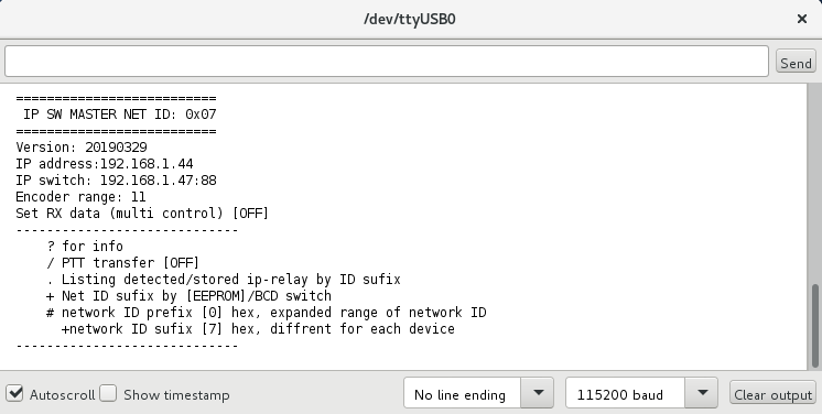
CLI contains some commands for set or show information.
- ? - show status
- / - enable/disable trasfer PTT (pin 18 on D-SUB connector) as one button (default number 8), may be change in firmware source edited with line
byte ButtonUseForPttTransfer= 8; // 1-8
- . - Listing detected/stored ip-relay by ID sufix, for switching between it
- + - Switch between source of network ID sufix eeprom/BCD switch
- # - set network ID prefix (four high bit) in hexadecimal format (0-f).
Configure
- Network-ID contains from two parts and defined pair device in network
- Prefix (four high bit) in hexadecimal format (0-f) set from CLI
- in standart mode prefix expanded range of network ID
- if enable Multi control, diffrent for each master device for his idetifications
- Sufix (four low bit) in hexadecimal format (0-f)
- get from eeprom or BCD switch depenency to preset in CLI
- in standart mode sufix diffrent for each device
- in Multi control mode same, for all shared devices (group id)
- NET-ID sufix set manualy via rotary BCD encoder in range 0-7
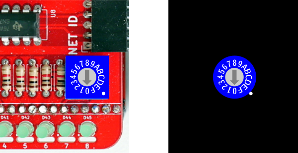
- if disable encoder in firmware, NET-ID sufix available preset from CLI in range 0-f (hex)
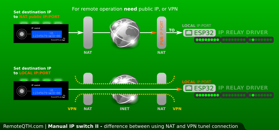
- Remotely IP address and UDP port, ouside from local network write directly to firmware. IP control use this address according to the setting NET-ID sufix (BCD switch or CLI). For remote operation need public IP or VPN
{0,0,0,0, 0}, // IP:port ID 0 {0,0,0,0, 0}, // IP:port ID 1 {0,0,0,0, 0}, // IP:port ID 2 {0,0,0,0, 0}, // IP:port ID 3 {0,0,0,0, 0}, // IP:port ID 4 {0,0,0,0, 0}, // IP:port ID 5 {0,0,0,0, 0}, // IP:port ID 6 {78,111,124,210, 88}, // IP:port ID 7 - remoteqth test point - I2C display need preset address in firmware
#define LcdI2Caddress 0x27
The most common are values 0x27 or 0x3F. If display dont work - Upload I2C scanner firmware
- Open terminal Ctrl+Shift+M
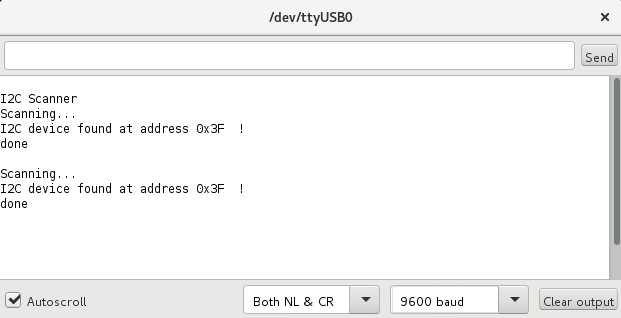
- Write detect addres to firmware
- Select I2C LCD chip
- If type of chip is PCF8574AT
- Install library LiquidCrystal_I2C
- Disable line
// #define LCD_PCF8574T
- If type of chip is PCF8574T
- Install library LiquidCrystal_PCF8574
- Enable line
#define LCD_PCF8574T
- If disable hardware BCD switch, NET-ID sufix available preset from CLI
#define HW_BCD_SW
- Debuging on serial terminal enable with
#define SERIAL_debug
- Fast power up, without shown LCD information enable with
#define FastBoot