Assembling Module -C- rev 0.4
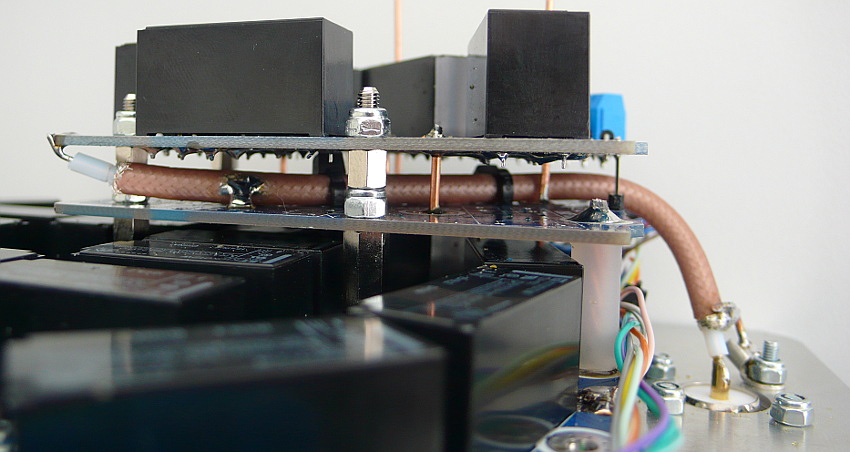
Module -C- is located above module -A- (as regards the second layer), otherwise over the previous module -C-.
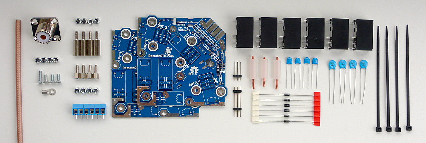
✔ All components
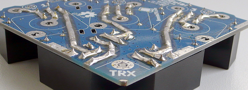
Shield board
❏ Screw the four 15 mm standoffs to the bottom Module -A-
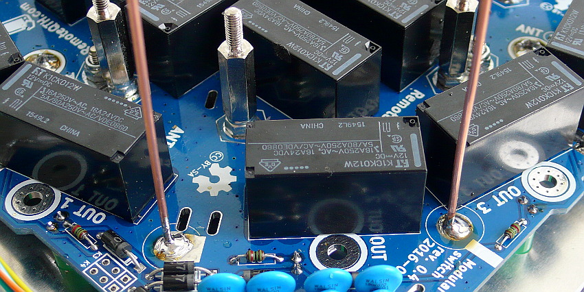
❏ Solder two grounded vertical wire - long depending on the number of installed level (aprox 40 mm on each) to the bottom Module -A- (GND output marked a thin ring).
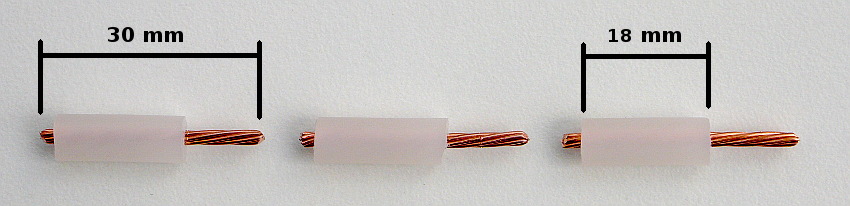
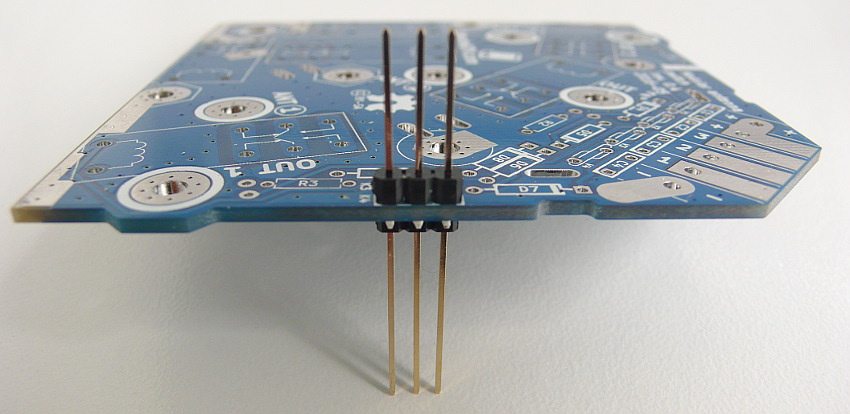
❏ Prepare three center wire from any strong coax cable (for example RG213) 30 mm long and cut isolation to remain at the length of 18 mm. Insulation use to separate VF and control line.
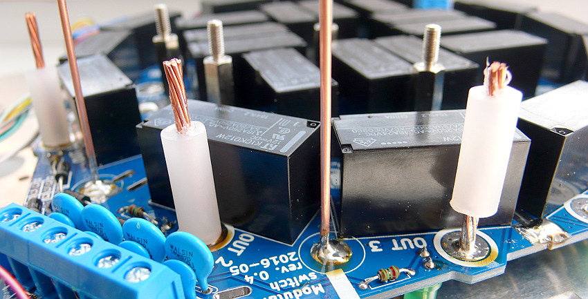
❏ After soldering long end to three VF outputs marked a strong ring insulation move down to PCB.
❏ If soldering in the second or higher-layer, check the overhang on the bottom side of the PCB, the wire does not protrude too and come close to the PCB beneath them.
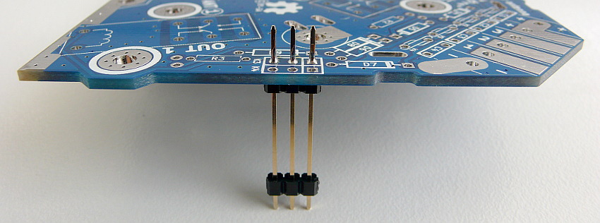
❏ Into an empty PCB, K3 slot deploy the longer end of the bottom solder three pins 30 mm debt.
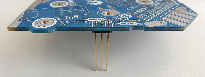
❏ Next cut the upper protruding pins and take off the bottom insulating grid.
❏ Solder three 18 mm pins from top PCB to K4 slot.
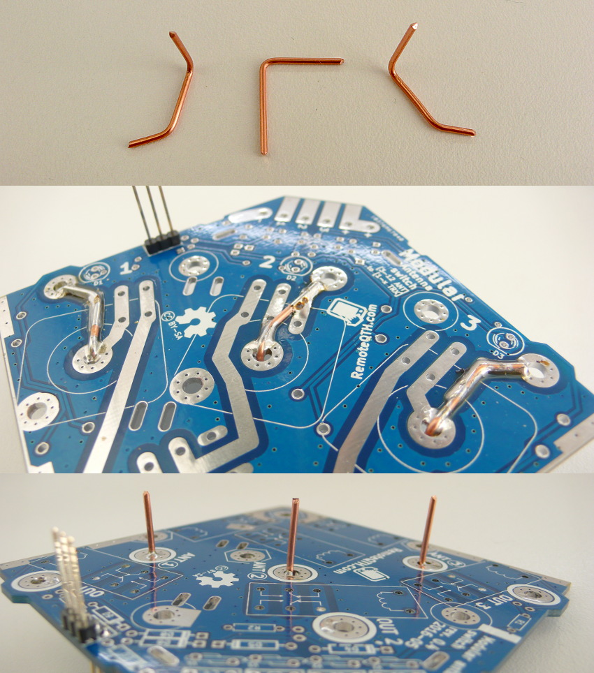
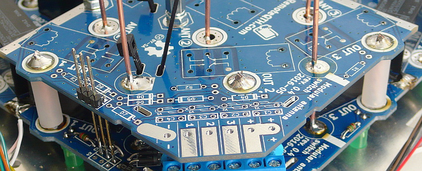
❏ Create three wire jumpers, after soldered to the PCB connects the input and output, and protrude 15 mm above the PCB.
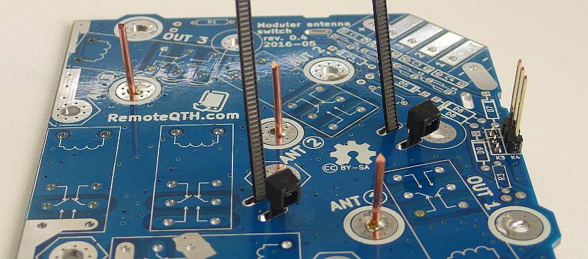
❏ Insert two strapping into slots in PCB
❏ Place the PCB on four screws and stretch all the wires, then screw with four locknut and 5 mm spacers.
❏ Test circuit with an ohmmeter before soldering.
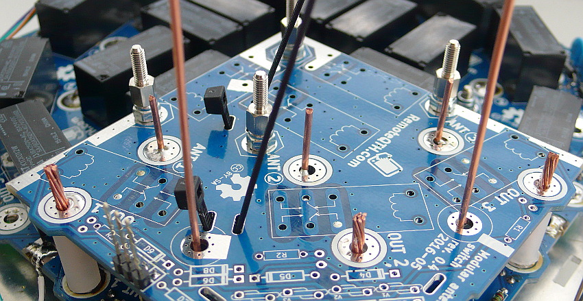
❏ After test, soldering two grounded wire and three VF - three VF line also cut the upper protruding wire. Grounded wire not cuting.
❏ Next solder three pins on K3 slots on the bottom PCB.
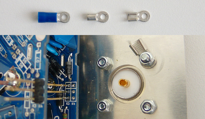
❏ Prepare solder eye and mount PL259 connector for second TRX.
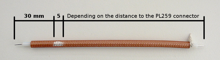
❏ To remove the insulation from the end RG142 coaxial cable and create 5 mm clear shielded for soldering to ground on PCB.
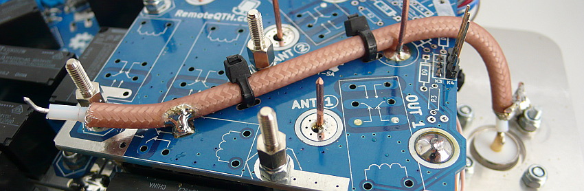
❏ Attach the coaxial with two strapping to PCB, and soldering ground point + end to coaxial connector.
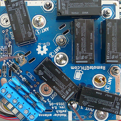
Switching board
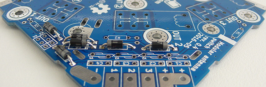
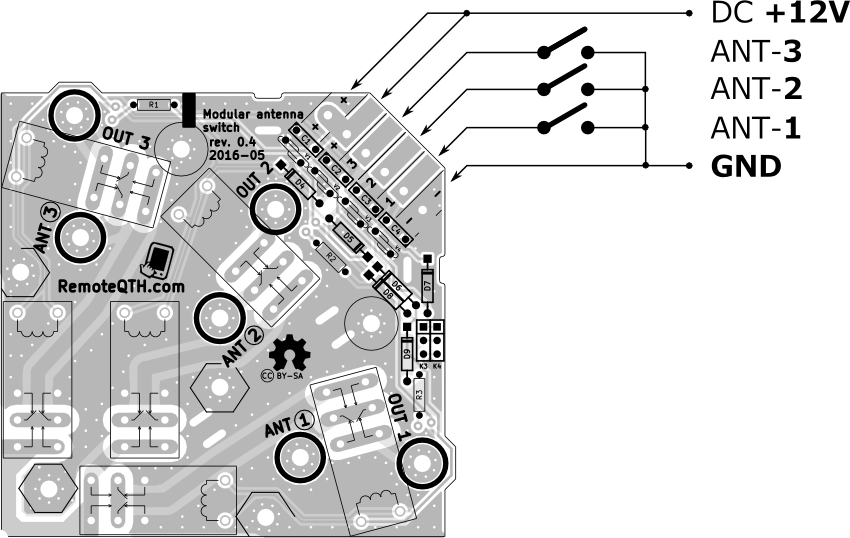
❏ Diode D4 D5 D6 D7 D8 necessary to observe polarity
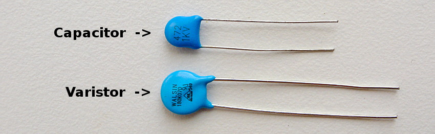
❏ What is the capacity and varistor. Capacity is marked 472. Varistor is marked 180K07D
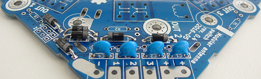
❏ capacity C1 C2 C3 C4
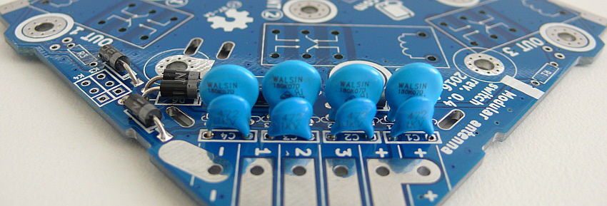
❏ varistor V1 V2 V3 V4
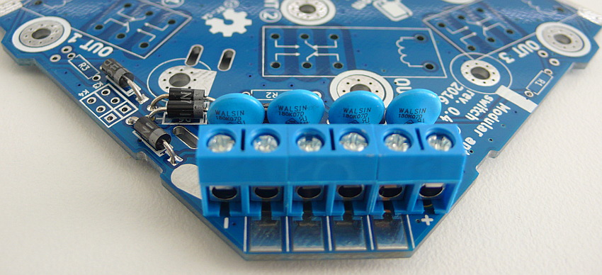
❏ Connector K1 K2
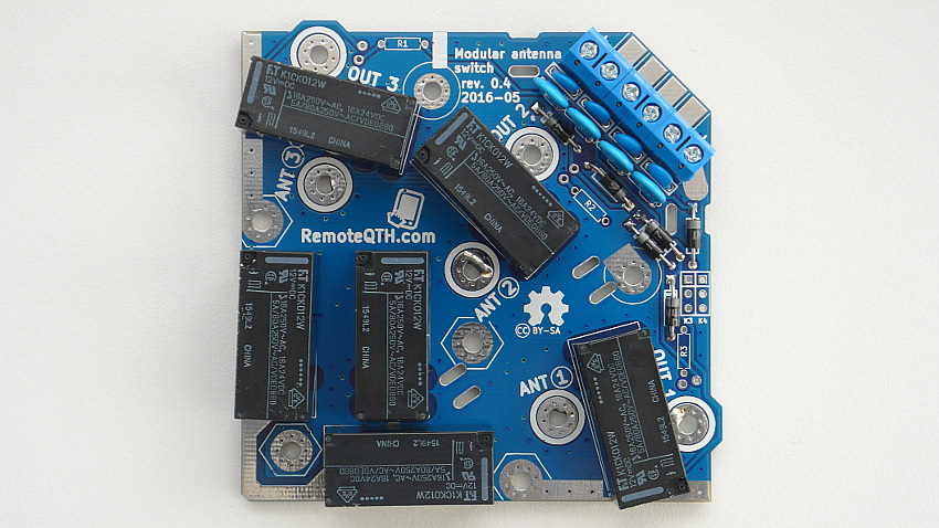
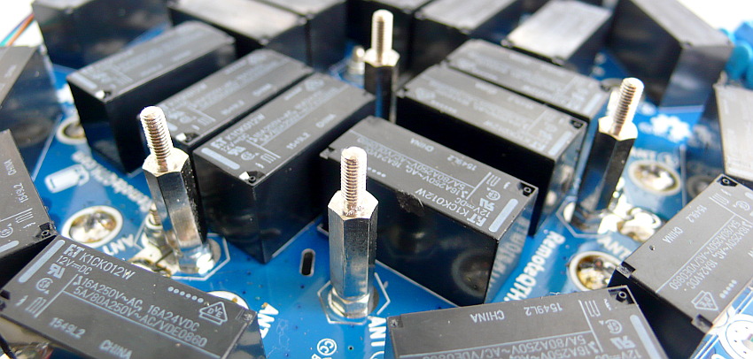
❏ Set soldering station to MAX 260°C and soldering relay RL1 RL2 RL3 RL4 RL5 RL6
❏ Because wire pins from relay are flat (not cylinder), you can avail the gap to shift relay more from the edge of the PCB that does not extend beyond the edge to the next module.
❏ Because of copper paths on the circuit board are rated at 8A, for the using of the full load relay until 16A it is necessary to apply a higher layer of tin on the unmasking of all RF paths.
❏ After deployment Switching board to shield PCB solder center coax to Switching board.
❏ Soldered two ground and three signal wire + mount four locknuts.
❏ Now module ready to connect control cable.