Band decoder MK2
← Old web page | Previous MK1 version
Quick start guide
- Kit soldering
- Preset and connect to TRX
- Upload firmware
- Box close
- Erata rev 1.0 by Gene K5PA, TNX! .pdf download
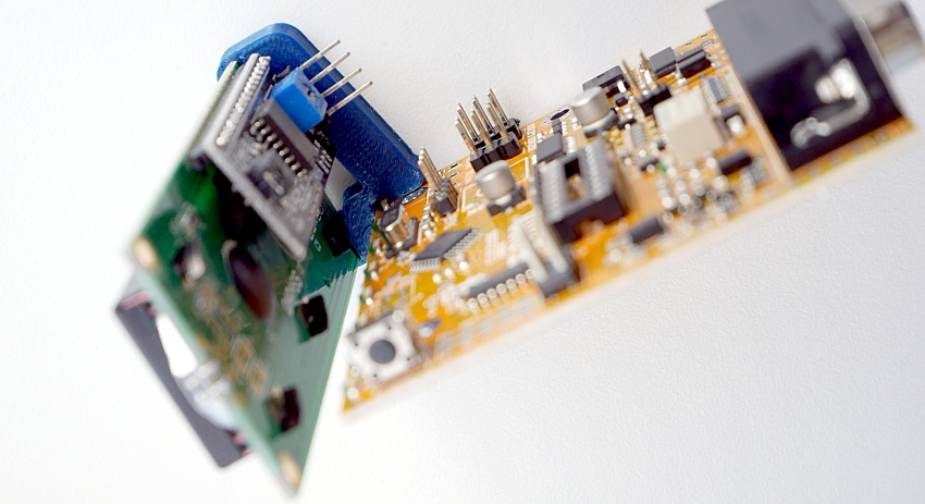
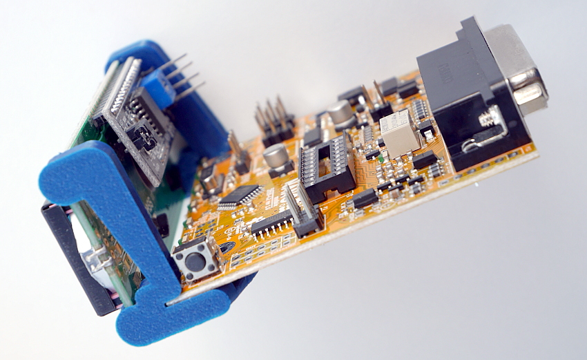
The hardware
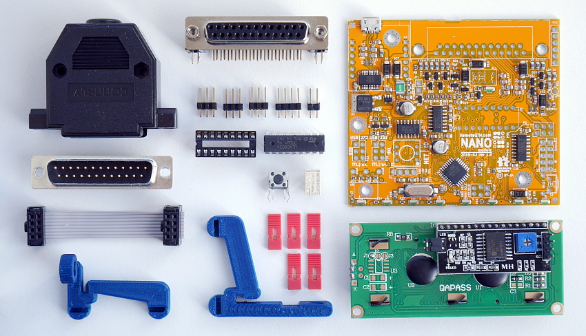
KIT is delivered with
- PCB with soldered all SMT parts
- preinstaled bootloader and simply 'snake' firmware lighting with all nine LED
- separate THT parts which you install in six steps
- I2C LCD display with 3D printed plastic holder
- Aluminium box
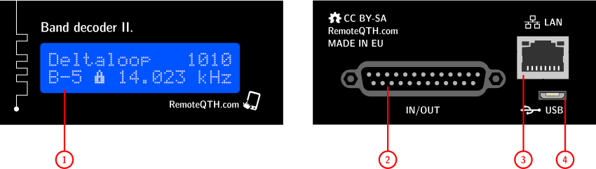
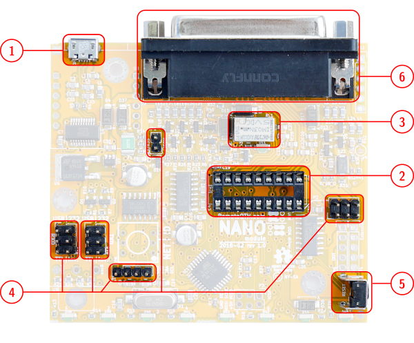
- 1 - status LCD display
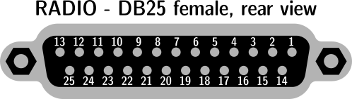
- 2 - 25 pin D-SUB inputs outputs
- 3 - Ethernet (optional) not implemented yet
- 4 - micro USB for upload firmware
Circuits
Based on universal NANO module
- rev 1.2
- rev 1.0
Changelog
- rev 1.2
- Relay Vin driver disconect from 12V and connect to pin23 D-SUB15
KIT assembly instructions
- First time connect USB to band decoder and your PC, and check (device manager in windows) that the USB converter has been recognized correctly. Contact us if you have any problems and do not continue assembly.
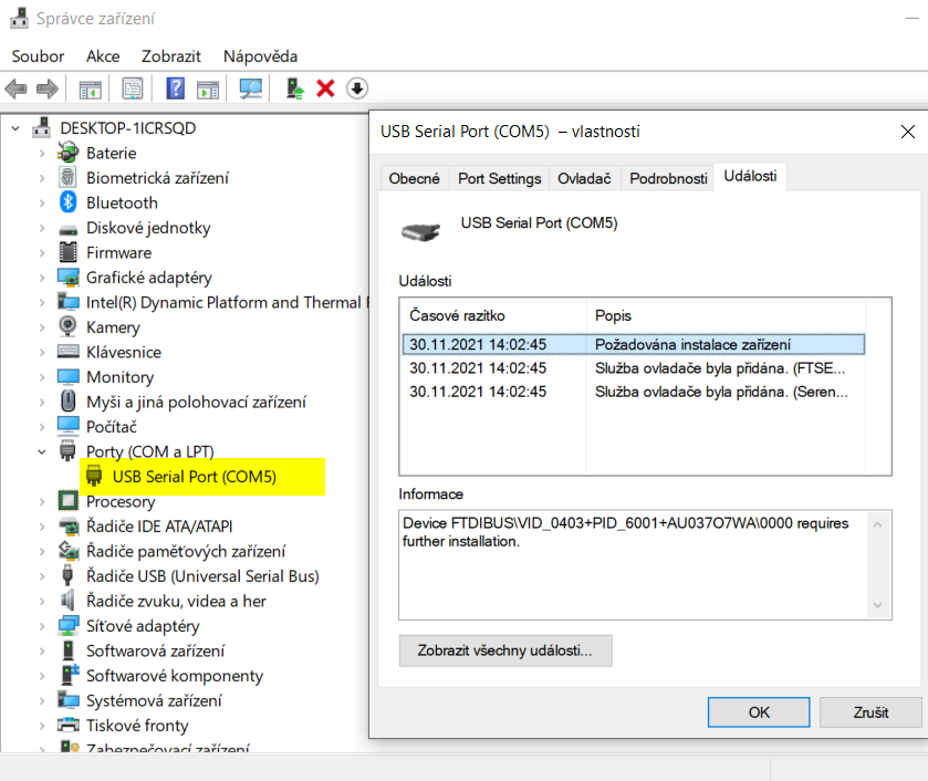
If detect right, you can continue.
All components
Soldering in six steps
- 1 - bottom pad J1 USB connector
- 2 - U5 DIL socket
- 3 - RL1 Relay
- 4 - P1 P2 P10 P11 JP1 Pin header
- 5 - S1 Reset button
- 6 - J2 D-SUB connector
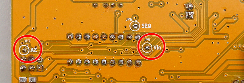
❏ Short JP5 JP7 SMD jumper padds on bottom side
❏ In version 1.2 the supply voltage of relay outputs is decoupled from the power supply of the device (open emitter) . If you want to use the same voltage short pin JP10. If you want a different voltage then you can put it in pin 23.
Display
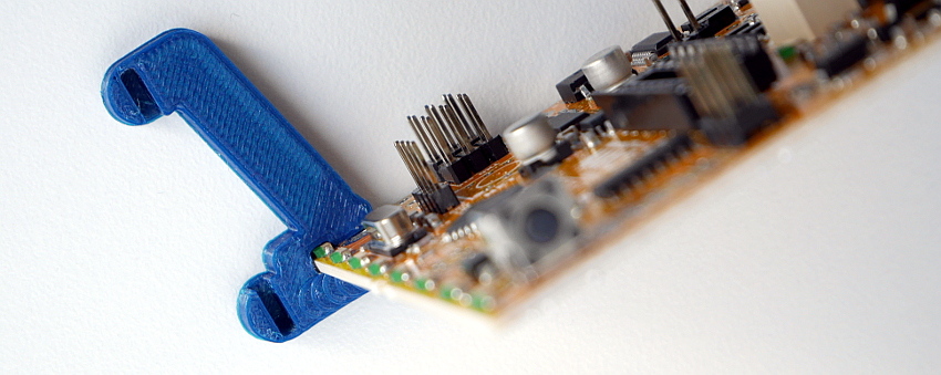
❏ Deploy from the left side Left LCD holder on PCB board
❏ Put LCD
❏ Deploy Right LCD holder on display and deploy to PCB from front side
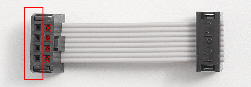
❏ Display cabe - on both side using only outside pins
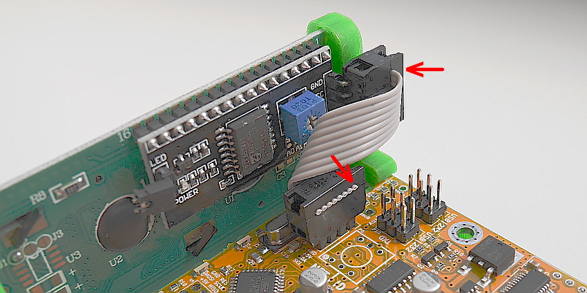
❏ Connect display and PCB board - Red arrow shows polarity
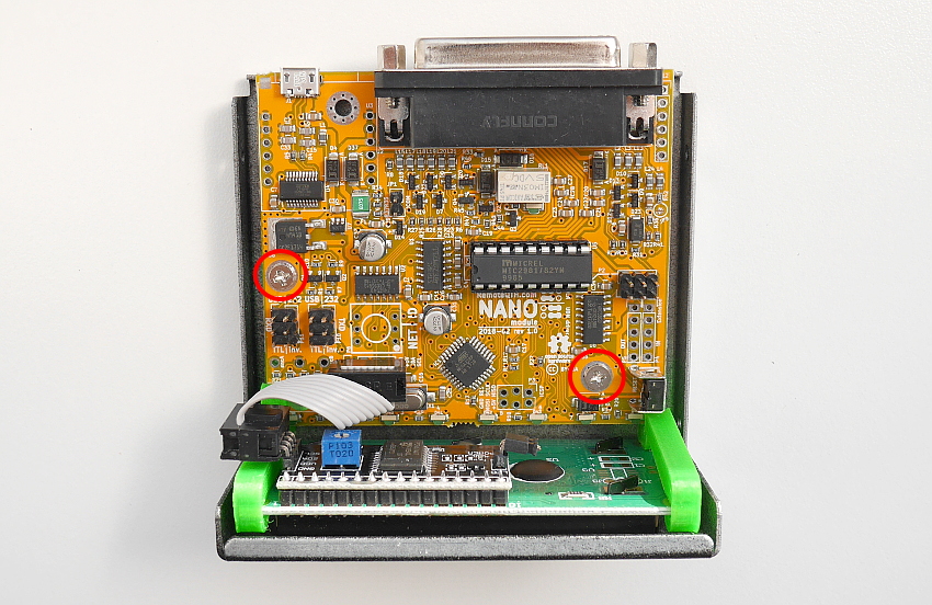
❏ Insert PCB with display to aluminium box and tighten with two screws
❏ I2C display need preset address in firmware
#define LcdI2Caddress 0x3F
The most common are values 0x27 or 0x3F.
- If display dont work
- Upload I2C scanner firmware
- Open terminal Ctrl+Shift+M
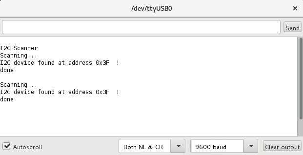
- Write detect addres to band decoder firmware
Select I2C LCD chip
- If type of chip is PCF8574AT
- Install library LiquidCrystal_I2C
- Disable line
// #define LCD_PCF8574T
- If type of chip is PCF8574T
- Install library LiquidCrystal_PCF8574
- Enable line
#define LCD_PCF8574T
❏ Preset LCD contrast with potentiometer on rear side LCD module
Power
❏ Connect power, typicaly 13,8V from transceiver
Configure output driver
We available two types of output drive
Open collector
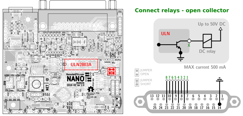
Using for components with grounding outputs
- Put in ULN2803A chip to U5 dil socket
- Set two jumpers in P2 to LEFT side
- board rev 1.0
- If relay voltage is higher than band decoder power supply (Vin), do not mount the upper jumper.
- board rev 1.2 and higher
- Connect relay power voltage also on pin23 J2-DB25 connector.
Open emiter
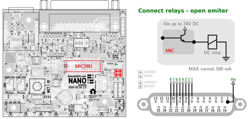
Using for components controlled with positive voltage
- Put in MIC2981 chip to U5 dil socket
- Set two jumpers in P2 to RIGHT side
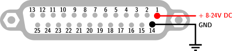
- Connect power for output control to pin1 in J2 D-SUB connector - this voltage use also for powered of band decoder and may be in range 8-24V
Configure outputs in firmware
- Allways enabled.
An entrance band data, or frequency, converts to output band 0-14 which can be configured in the following table - Preset Band to output matrix - in default settings Band-1 corresponds to Output-1, etc. You can sets any combination outputs for each band separately. With change zeros and ones in the Matrix table. Band-0 reserved for out of range inputs measure.
//=====[ Sets band -->  to output in MATRIX table ]===========================================================

        const boolean matrix[17][16] = { /*

        Band 0 --> */ { 0,  0,  0,  0,  0,  0,  0,  0,    0,  0,  0,  0,  0,  0,  0,  1 }, /* first eight shift register board
\       Band 1 --> */ { 1,  0,  0,  0,  0,  0,  0,  0,    0,  0,  0,  0,  0,  0,  0,  0 }, /*
 \      Band 2 --> */ { 0,  1,  0,  0,  0,  0,  0,  0,    0,  0,  0,  0,  0,  0,  0,  0 }, /*
  \     Band 3 --> */ { 0,  0,  1,  0,  0,  0,  0,  0,    0,  0,  0,  0,  0,  0,  0,  0 }, /*
   \    Band 4 --> */ { 0,  0,  0,  1,  0,  0,  0,  0,    0,  0,  0,  0,  0,  0,  0,  0 }, /*
    \   Band 5 --> */ { 0,  0,  0,  0,  1,  0,  0,  0,    0,  0,  0,  0,  0,  0,  0,  0 }, /*
     \  Band 6 --> */ { 0,  0,  0,  0,  0,  1,  0,  0,    0,  0,  0,  0,  0,  0,  0,  0 }, /*
IN    ) Band 7 --> */ { 0,  0,  0,  0,  0,  0,  1,  0,    0,  0,  0,  0,  0,  0,  0,  0 }, /*
     /  Band 8 --> */ { 0,  0,  0,  0,  0,  0,  0,  1,    0,  0,  0,  0,  0,  0,  0,  0 }, /*

    /   Band 9 --> */ { 0,  0,  0,  0,  0,  0,  0,  0,    1,  0,  0,  0,  0,  0,  0,  0 }, /* second eight shift register board
   /    Band 10 -> */ { 0,  0,  0,  0,  0,  0,  0,  0,    0,  1,  0,  0,  0,  0,  0,  0 }, /* (optional)
  /     Band 11 -> */ { 0,  0,  0,  0,  0,  0,  0,  0,    0,  0,  1,  0,  0,  0,  0,  0 }, /*
 /      Band 12 -> */ { 0,  0,  0,  0,  0,  0,  0,  0,    0,  0,  0,  1,  0,  0,  0,  0 }, /*
/       Band 13 -> */ { 0,  0,  0,  0,  0,  0,  0,  0,    0,  0,  0,  0,  1,  0,  0,  0 }, /*
        Band 14 -> */ { 0,  0,  0,  0,  0,  0,  0,  0,    0,  0,  0,  0,  0,  1,  0,  0 }, /*
        Band 15 -> */ { 0,  0,  0,  0,  0,  0,  0,  0,    0,  0,  0,  0,  0,  0,  1,  0 }, /*
        Band 16 -> */ { 0,  0,  0,  0,  0,  0,  0,  0,    0,  0,  0,  0,  0,  0,  0,  1 }, /*
                        |   |   |   |   |   |   |   |     |   |   |   |   |   |   |   |
                        V   V   V   V   V   V   V   V     V   V   V   V   V   V   V   V
                     ----------------------------------  ---------------------------------
                     |  1   2   3   4   5   6   7   8     9  10  11  12  13  14  15  16  |
                     ----------------------------------  ---------------------------------
                                                   OUTPUTS */
Outputs only eight, for next need aditional board.
PTT
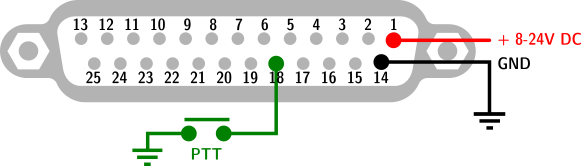
- If PTT input (pin-18 25D-SUB) connect to ground, changing the switching outputs are blocked.
- PTT output (pin-6 25D-SUB) may be use for interruption PTT path for example to power amplifier, if frequency out of band, or not available.
Pinouts 25 pin D-SUB
| pin-1 | in | Input power 8-18V DC from Transceiver |
| pin-2 | in | ICOM CI-V |
| pin-3 | out | TXD TTL |
| pin-4 | out | TXD TTL inverted |
| pin-5 | out | TXD 232 level |
| pin-6 | out | PTT output |
| pin-7 | out | Relay 2 |
| pin-8 | out | Relay 4 |
| pin-9 | out | Relay 6 |
| pin-10 | out | Relay 8 |
| pin-11 | in/out | BCD4 |
| pin-12 | in/out | BCD2 |
| pin-13 | in | AZ |
| pin-14 | - | GND |
| pin-15 | in | RXD TTL |
| pin-16 | in | RXD TTL inverted |
| pin-17 | in | RXD 232 level |
| pin-18 | in | PTT in |
| pin-19 | out | Relay 1 |
| pin-20 | out | Relay 3 |
| pin-21 | out | Relay 5 |
| pin-22 | out | Relay 7 |
| pin-23 rev1.0 | out | +5V |
| pin-23 rev1.2 | in | Relay Vin |
| pin-24 | in/out | BCD3 |
| pin-25 | in/out | BCD1 |
| shield | - | GND |
Firmware
- Read first erata rev 1.0 by Gene K5PA, TNX! .pdf download
- Download and install Arduino IDE
- Install library
- Wire
- LiquidCrystal_I2C or LiquidCrystal_PCF8574
- Download Band Decoder 2 firmware source from GitHub
- Preset two jumper in P10/P11 pin geader
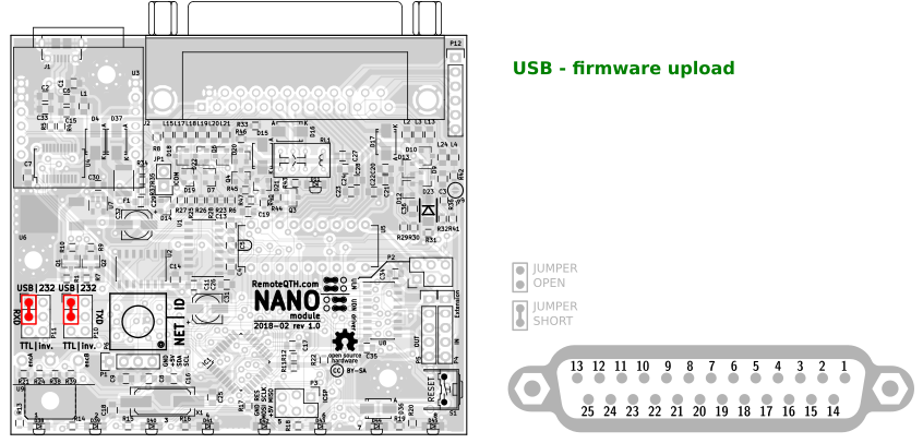
- Connect micro USB cable between band decoder and PC
- Configure... (more in the chapter Configure TRX inputs)
- Select menu Tools/Board:Arduino Nano
- Select menu Tools/Processor: ATmega328P or ATmega328P(Old Bootloader) at older PCB version.
- Select menu Tools/Port/YOUR-CONNECTED-PORT
- Upload firmware
Multiple output
Standart operation is each band has one output.
If enable line
#define MULTI_OUTPUT_BY_BCDin firmware source, each band can have up to four outputs, selectable by BCD inpit pins. These conditions need to be set
- YAESU_BCD input must be disable
- BCD output will be disble
- select (grounded) one of BCD input for select
Otput set in matrix table
- Each bcd input represent by bit in this table
- 0x01 = B00000001 = bit 1
- 0x02 = B00000010 = bit 2
- 0x04 = B00000100 = bit 3
- 0x08 = B00001000 = bit 4
- For example record
Band 1 --> { 0x01, 0x02, 0x04, 0, 0x08, 0, 0, 0, 0, 0, 0, 0, 0, 0, 0, 0 },is the same as recordBand 1 --> { B00000001, B00000010, B00000100, 0, B00001000, 0, 0, 0, 0, 0, 0, 0, 0, 0, 0, 0 }, - 0x0F = this output enable for any BCD input (enable all bit)
LCD antenna name set in array for each bcd input separately
const char* ANTname[17][4] = {
      {"Out of band", "Out of band", "Out of band", "Out of band"},  // Band 0 (no data)
      {"Dipole", "BCD-2", "BCD-3", "BCD-4"},       // Band 1
      {"Vertical", "BCD-2", "BCD-3", "BCD-4"},     // Band 2
      {"3el Yagi", "BCD-2", "BCD-3", "BCD-4"},     // Band 3
      ...
CONFIGURE INPUTS
Individual functionality is enable or disable with coment/uncoment preset line
First sets global frequency rules which they choose BAND number by frequency with a resolution of one Hz. Also may be use for partition one band to more subbands.
//Freq Hz from       to   Band number
     {1810000,   2000000},  // #1 [160m]
     {3500000,   3800000},  // #2  [80m]
     {7000000,   7200000},  // #3  [40m]
    {10100000,  10150000},  // #4  [30m]
    {14000000,  14350000},  // #5  [20m]
    {18068000,  18168000},  // #6  [17m]
    {21000000,  21450000},  // #7  [15m]
    {24890000,  24990000},  // #8  [12m]
    {28000000,  29700000},  // #9  [10m]
    {50000000,  52000000},  // #10  [6m]
   {144000000, 146000000},  // #11  [2m]
   {430000000, 440000000},  // #12  [70cm]
   {1240000000, 1300000000},  // #13  [23cm]
   {2300000000, 2450000000},  // #14  [13cm]
   {3300000000, 3500000000},  // #15  [9cm]
   {5650000000, 5850000000},  // #16  [6cm]
Second uncomment and activate only one input in source code
//=====[ Inputs ]=============================================================================================

// #define ICOM_CIV           // read frequency from CIV
// #define KENWOOD_PC         // RS232 CAT
//#define YAESU_BCD          // TTL BCD in A
// #define ICOM_ACC           // voltage 0-8V on pin4 ACC(2) connector - need calibrate table
// #define INPUT_SERIAL       // telnet ascii input - cvs format [band],[freq]\n
// #define YAESU_CAT          // RS232 CAT YAESU CAT since 2015 ascii format
// #define YAESU_CAT_OLD      // Old binary format RS232 CAT ** tested on FT-817 **
And connect to TRX as described below
Available Inputs
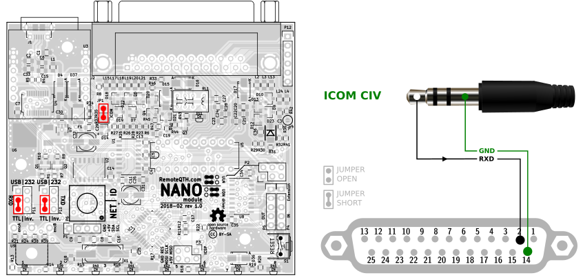
Icom CI-V
- Activate uncomment line
#define ICOM_CIV
- And settings with
#define SERBAUD        9600  // [baud] Serial port in/out baudrate
#define WATCHDOG       10    // [sec] determines the time, after which the all relay OFF, if missed next input data - uncomment for the enabled
#define REQUEST        500     // [ms] use TXD output for sending frequency request
#define CIV_ADRESS   0x56  // CIV input HEX Icom adress (0x is prefix)
- short JP1
- short P10 left/down
- short P11 left/down
- Connect trough two wire line
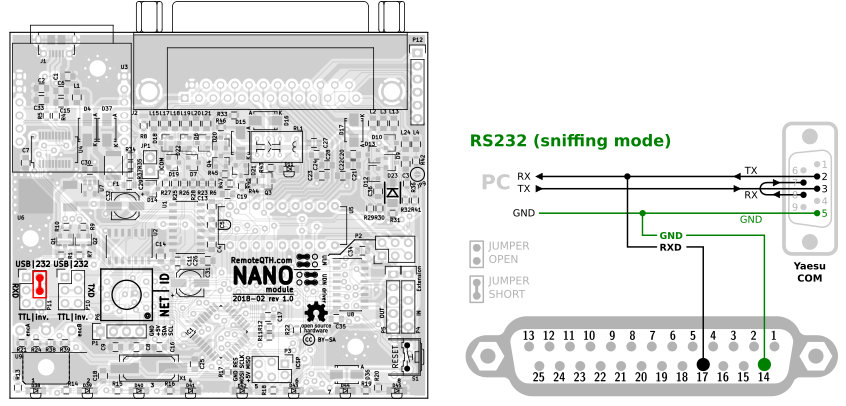
Kenwood/Elecraft RS232
- Activate uncomment line
#define KENWOOD_PC
- And settings with
#define SERBAUD        9600  // [baud] Serial port in/out baudrate
#define WATCHDOG       10    // [sec] determines the time, after which the all relay OFF, if missed next input data - uncomment for the enabled
#define REQUEST        500     // [ms] use TXD output for sending frequency request
Sniffing mode
- short P11 right/top
- Connect trough two wire line
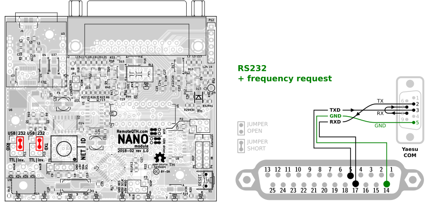
Request mode
- short P10 right/top
- short P11 right/top
- Connect trough three wire line
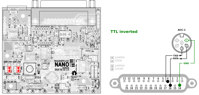
Kenwood (old) TS-x50 inverted TTL
- short P10 right/bottom
- short P11 right/bottom
- Connect trough three wire line
FLEX-6000 RS-232
Need USB/232 interface - see in manual guide
- Activate uncomment line
#define FLEX_6000
and connecting same as Kenwood
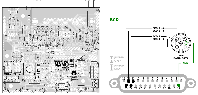
YAESU/General BCD
- Activate uncomment line
#define YAESU_BCD
- Connect trough five wire line
Icom ACC voltage
Hardware dependency
- Open JP6 SMT pad on bottom side of PCB
- Short JP7 SMT pad on bottom side of PCB
- Short JP9 SMT pad on bottom side of PCB - must be, else risk damage the procesor.
How to calibrate
- After make hardware dependency
- Connect trough two wire line voltage from TRX to pin13 on DB25 connector according to picture
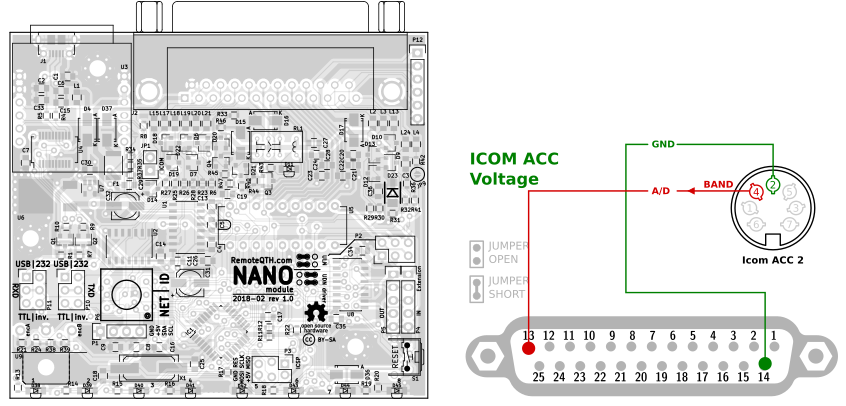
- Activate uncomment line
#define ICOM_ACC
- need disable watchdog
// #define WATCHDOG 10 // [sec] determines the time, after which the all relay OFF, if missed next input data - uncomment for the enabled
- Upload firmware
- Read voltage from LCD by band, and preset rules in table
//=====[ Icom ACC voltage range ]=========================================================== if (AccVoltage > 0.73 && AccVoltage < 1.00 ) {BAND=10;} // 6m * * * * * * * * * * * * * * * * if (AccVoltage > 1.00 && AccVoltage < 1.09 ) {BAND=9;} // 10m * Need * if (AccVoltage > 1.09 && AccVoltage < 1.32 ) {BAND=8;} // 12m * calibrated to your * if (AccVoltage > 1.32 && AccVoltage < 1.55 ) {BAND=7;} // 15m * own ICOM * if (AccVoltage > 1.55 && AccVoltage < 1.77 ) {BAND=6;} // 17m * ---------------- * if (AccVoltage > 1.77 && AccVoltage < 2.24 ) {BAND=5;} // 20m * (These values have * if (AccVoltage > 0.10 && AccVoltage < 0.50 ) {BAND=4;} // 30m * been measured by any) * if (AccVoltage > 2.24 && AccVoltage < 2.73 ) {BAND=3;} // 40m * ic-746 * if (AccVoltage > 2.73 && AccVoltage < 2.99 ) {BAND=2;} // 80m * * if (AccVoltage > 2.99 && AccVoltage < 4.00 ) {BAND=1;} // 160m * * * * * * * * * * * * * * * * if (AccVoltage > 0.00 && AccVoltage < 0.10 ) {BAND=0;} // parking //========================================================================================== - Upload firmware again
- Precise calibrate value reach with measure voltage on Aref input (C17) and insert to code
float ArefVoltage = 4.228; // Measure on Aref pin 20 for calibrate
YAESU CAT
- Activate uncomment line
#define YAESU_CAT
- And settings with
#define SERBAUD        9600  // [baud] Serial port in/out baudrate
#define WATCHDOG       10    // [sec] determines the time, after which the all relay OFF, if missed next input data - uncomment for the enabled
#define REQUEST        500     // [ms] use TXD output for sending frequency request
Sniffing mode
- short P11 right/top
- Connect trough two wire line
Request mode
- short P10 right/top
- short P11 right/top
- Connect trough three wire line
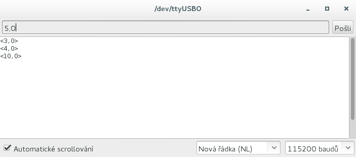
Input Serial
Activate uncomment line
#define INPUT_SERIAL
- Disable watchdog
// #define WATCHDOG 10 // [sec] determines the time, after which the all relay OFF, if missed next input data - uncomment for the enabled
Not need any hardware settings, only send via USB to serial line ascii characters in preconfigured baudrate.
X,YYYYYYY\n
- X - band output in range 0-14, if activate BCD output range is 0-10 because 11-14 reserved for BCD. 0 (zero) = no output will be turned on.
- YYYYYYY - frequency in Hz - has no effect on the output relays, used if any CIV/CAT outputs activated.
- \n - is LF Line Feed (0A in hex)
CONFIGURE OUTPUTS
You can uncomment more than one output, but not all combinations are worked.
Always usable - may all at once.
- 8 output driver - allways enabled
- Yaesu BCD - allways enabled except activate Yaesu BCD input
- Serial echo
Only one from (not available during active Frequency request option (available only one TXD line)
//=====[ Outputs ]============================================================================================
// #define SERIAL_echo        // Feedback on serial line in same baudrate, CVS format <[band],[freq]>\n
// #define ICOM_CIV_OUT       // send frequency to CIV ** you must set TRX CIV_ADRESS, and disable ICOM_CIV **
// #define KENWOOD_PC_OUT     // send frequency to RS232 CAT ** for operation must disable REQUEST **
// #define YAESU_CAT_OUT      // send frequency to RS232 CAT ** for operation must disable REQUEST **
8 output driver
- Allways enabled.
How to expand outputs
Band decoder use internal shift register with 8 outputs. This is free expandable. You can connect next shift register to P5 output connector. Schematics module for serial chain linkink on picture.
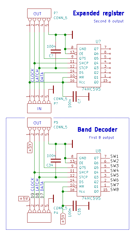
And sets number of all shift register in firmware
- internal = 1
- internal + one external =2
int NumberOfBoards = 2; // number of eight byte shift register 0-x
SERIAL ECHO
Activate uncomment line
#define SERIAL_echo
Requires setting
#define SERBAUD 9600
YAESU BCD output
Always activate - except enable BCD input.
You can set rules to select BCD output, dependency to detected band input.
//=====[ BCD OUT ]===========================================================================================

        const boolean BCDmatrixOUT[4][16] = { /*
        --------------------------------------------------------------------
        Band # to output relay   0   1   2   3   4   5   6   7   8   9  10
        (Yaesu BCD)                 160 80  40  30  20  17  15  12  10  6m
        --------------------------------------------------------------------
                                 |   |   |   |   |   |   |   |   |   |   |
                                 V   V   V   V   V   V   V   V   V   V   V
                            */ { 0,  1,  0,  1,  0,  1,  0,  1,  0,  1,  0, 1, 0, 1, 0, 1 }, /* --> DB25 Pin 11
                            */ { 0,  0,  1,  1,  0,  0,  1,  1,  0,  0,  1, 1, 0, 0, 1, 1 }, /* --> DB25 Pin 24
                            */ { 0,  0,  0,  0,  1,  1,  1,  1,  0,  0,  0, 0, 1, 1, 1, 1 }, /* --> DB25 Pin 12
                            */ { 0,  0,  0,  0,  0,  0,  0,  0,  1,  1,  1, 1, 1, 1, 1, 1 }, /* --> DB25 Pin 25
        */};

//============================================================================================================
ICOM CIV output
Activate uncomment line
#define ICOM_CIV_OUT
Requires baud rate and CIV address in setting section of source code
#define SERBAUD      9600    // [baud] Serial port in/out baudrate
#define CIV_ADR_OUT  0x56    // HEX Icom adress (0x is prefix)
- short JP1 left (TXD)
KENWOOD CAT output
Activate uncomment line
#define KENWOOD_PC_OUT
Requires baud rate in setting section of source code
#define SERBAUD 9600 // [baud] Serial port in/out baudrate
- short JP1 right (TXD)
- short JP7
YAESU CAT output
Activate uncomment line
#define YAESU_CAT_OUT
Requires baud rate in setting section of source code
#define SERBAUD 9600 // [baud] Serial port in/out baudrate
- short JP1 right (TXD)
- short JP7
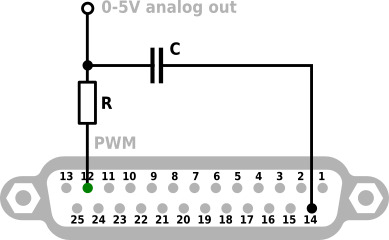
PWM (Analog) output
Activate uncomment line
#define PWM_OUT
PWM signal output is on pin 12, DB-25 connector. For convert to analog voltage 0-5V need add RC filter to this output.
- R 10k
- C 10uF
For each band set PWM output (range 0-255) in table
  const long PwmByBand[16] = {/*
  PWM 0-255
  */ 0,    // #0  OUT of band
     15,   // #1  [160m]
     30,   // #2  [80m]
     45,   // #3  [60m]
     45,   // #4  [40m]
     60,   // #5  [30m]
     75,   // #6  [20m]
     90,   // #7  [17m]
     105,  // #8  [15m]
     120,  // #9  [12m]
     135,  // #10 [10m]
     150,  // #11 [6m]
     165,  // #12 [4m]
     180,  // #13 [2m]
     195,  // #14 [70cm]
     210,  // #15 [23cm]
     225,  // #17 [13cm]
  };
After assembly, measure the output voltage and adjust the PWM values according to your requirements.
Warning: the output is high impedance, a load of low impedance will affect the output voltage. You can use an OP-AMP buffer for low impedances.
Debug mode
Allows read comunications and show in terminal
- Enable debug in firmware
#define DEBUG
- Enable inputs by connected radio
//=====[ Inputs ]=============================================================================================
// #define YAESU_BCD          // TTL BCD in A
// #define ICOM_ACC           // voltage 0-8V on pin4 ACC(2) connector - need calibrate table
// #define INPUT_SERIAL       // telnet ascii input - cvs format [band],[freq]\n
// #define ICOM_CIV           // read frequency from CIV
// #define KENWOOD_PC         // RS232 CAT
// #define YAESU_CAT          // RS232 CAT YAESU CAT since 2015 ascii format
// #define YAESU_CAT_OLD      // Old binary format RS232 CAT ** tested on FT-817 **
- Upload firmware
- Preset RXD P11 dependency to connected transceiver
- 232 for RS232 communications
- TTL for 5V level data
- Preset P10 to USB
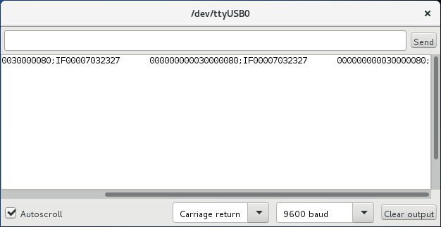
- Open arduino terminal, and set same baudrate by firmware preset
#define SERBAUD 9600
- Sniffing communications (on picture Kenwood CAT)...