K9AY feeder with BPF
- Quick Start Guide
- Antenna loop design
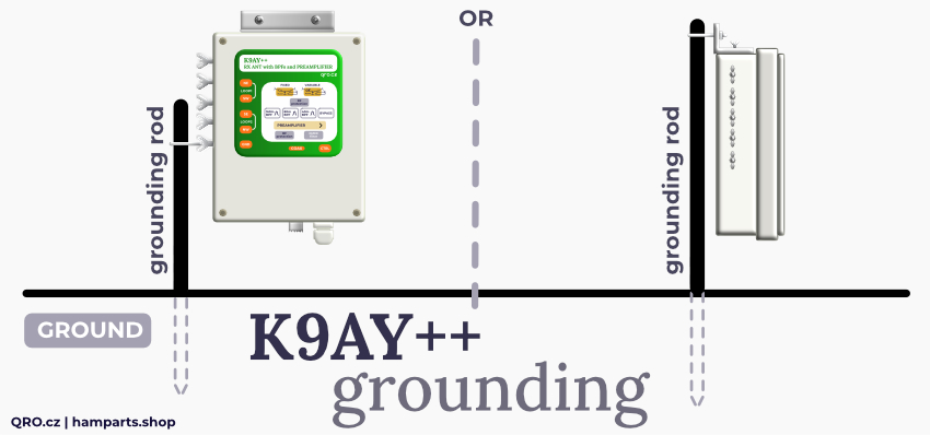
- Antenna GROUND
- Locating Your K9AY Loops
- Loop connection
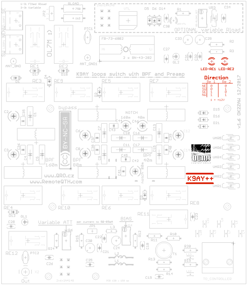
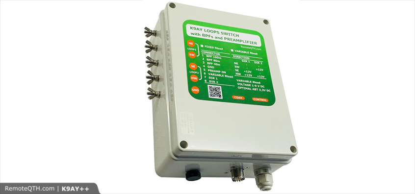
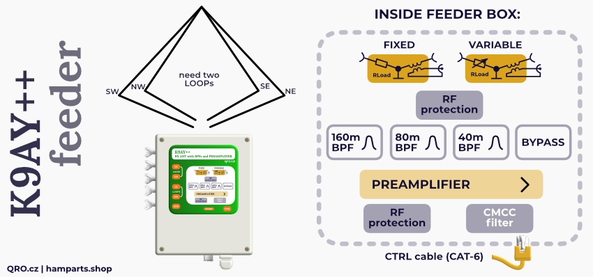
- What is inside
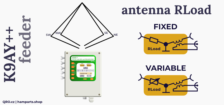
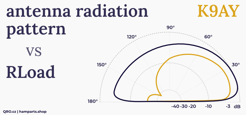
- Variable and Fixed Rload resistor
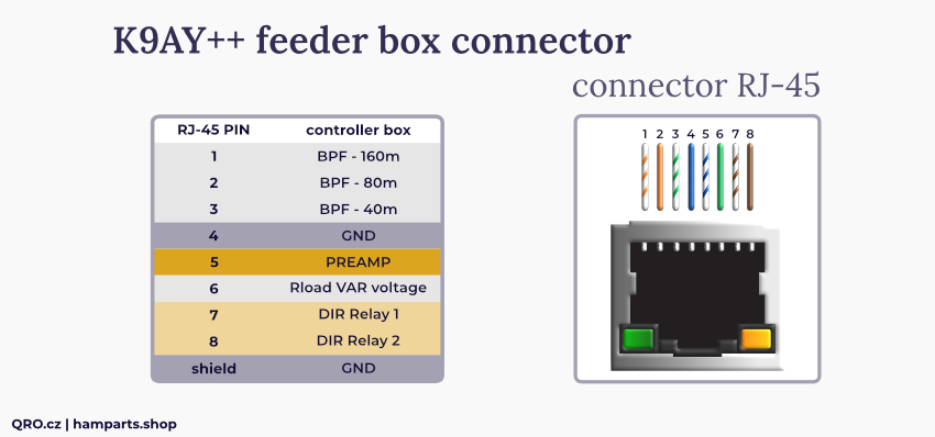
- Connector description
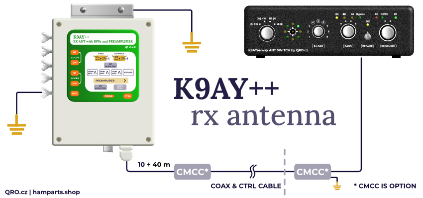
- Common mode filter for coax and controller cable
- Rload FIXed or VARiable
- Rload checking the resistance
- Preamp BIAS SET check current and voltage
- Preamp GAIN set
- Direction switching check
This is plastic box with the aluminium holder. Inside it, there is transformer with insulated windings, variable and FIXed Rload for the antenna loop, input and output protections. And in the middle of that thare are 160/80/40m BPFs or bypass and 15dB preamp with variable ATT. You can set the Gain of the preamp very easy as you need. From 0 to 18 dB.
All you need is connect loops' wires, GND, coax cable and control cable (CAT-5 UTP or better FTP)
Quick Start Guide
- Youtube videos - lsn to K9AY
- K9AY LOOPs design - more size variants
- OPTION: Common-mode filter for coax and controller cable
- CONTROLLER - instructions
- What is inside - Description
- Variable and Fixed Rload resistor - Loop Load resistor
- Connector description - RJ45 connector
- Locating Your K9AY Loops
- Antenna ground
- Loop connection
- Rload - FIXed / VARiable
- Rload - checking the resistance
- Preamp BIAS - SET/check current and voltage
- Preamp GAIN
- Direction switching check
Antenna loop design
- There are some loop designs + MMANA files. You can play with the size and shape by yourself too.
- K9AY LOOPs design - more size variants
Antenna GROUND
- The K9AY antenna doesn't work without ground.
- It loses the f/b directivity.
- This means that it needs good ground!
- A 4-foot ground rod (such as 3/4” diameter copper pipe) is often sufficient. If the earth is very dry, a longer ground rod is advised, to reach permanently moist earth—or you may install four or more 15- to 20-foot long radial wires for better coupling to ground. The grounded design of the K9AY Loop has several advantages over ground-independent versions of the terminated loop (Pennant and Flag), including simpler switching, no feedline isolation problems, and greater signal capture for the same size loops. source K9AY: AY Technologies
Connecting the GND
- As you can see on the pictures, there is common GND on the screw under loops connections and also on the aluminium holder.
- You can mount box directly on the GND rod.
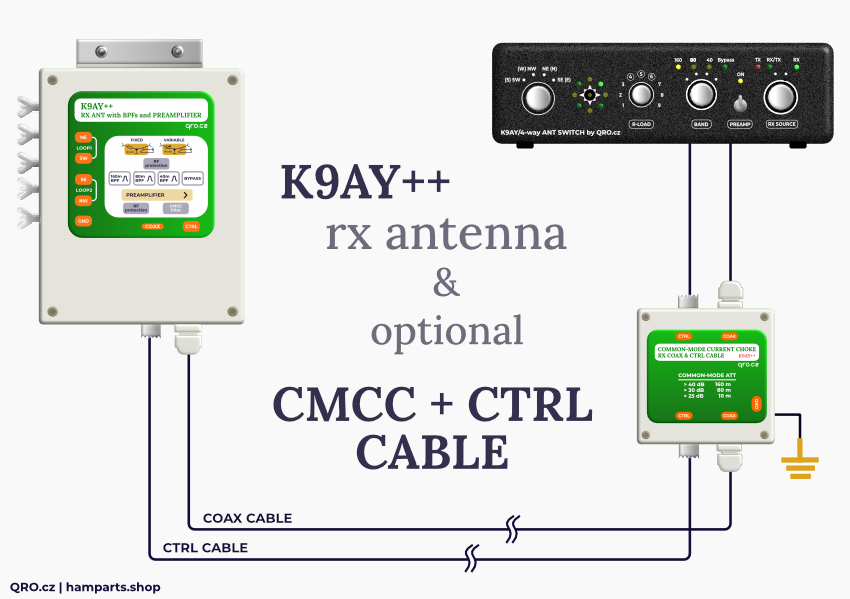
- CMCC - Common-mode current chokes: are recommended for Coax and control cable.
Locating Your K9AY Loops
- Since you have chosen a small receiving antenna, it is likely that your transmitting antenna will be nearby. Transmitting antennas, power lines, towers and other nearby large conducting objects can re-radiate signals that are coupled to the receiving antenna. To avoid this problem, locate the K9AY Loop as far from the transmitting antenna as possible. Because the loop is small, it is often possible to place it among trees or shrubs in a front or side yard, while the transmitting antenna is in back. Another way to minimize the interaction is to locate the loop toward the most important direction you want to hear. For example, if you are most interested in hearing Europe from the US, locate the loop Northeast of the transmitting antenna. When pointed toward Europe, the null will be in the direction of the transmitting antenna, reducing the pickup of re-radiated signals. Some European users of the K9AY Loop have chosen single loops, placing one of them Northwest of the transmitting antenna to hear US stations, with another East or Northeast to hear Asia and the Far East. source K9AY: AY Technologies
- Controller is universal for 0 or 45 deg orientation: more info there
Loop connection
- This is very important thing which has effect on final antenna parameters
- If you end lower part of loops as close to ground as possible, you can obtain better F/B.
- Install RF feeder box higher - protect from snow, water etc and connect loops with twisted wires from loops to screws
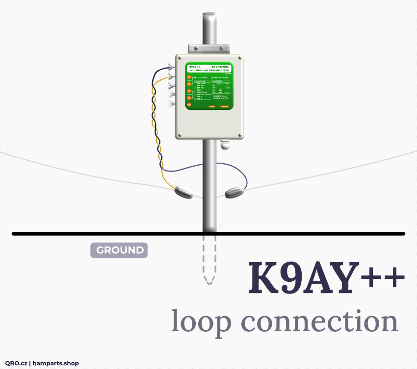
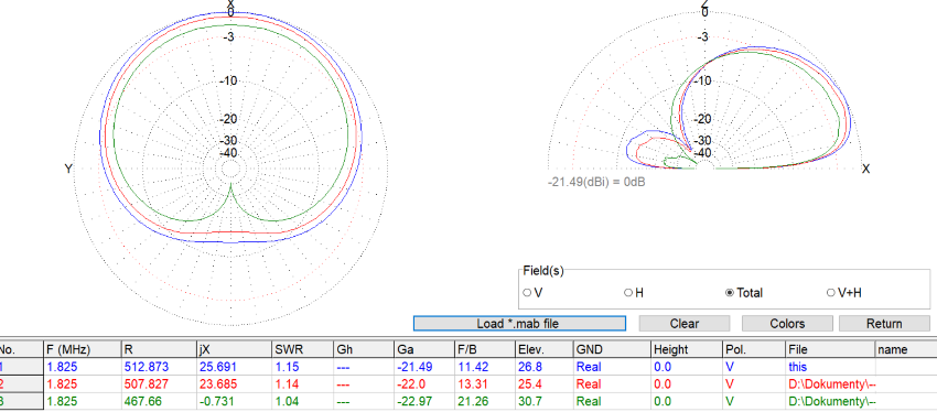
- Effect of low part of loops
- Place loops as low as possible
- GREEN = on ground, RED = 0,5m, BLUE = 0,8m
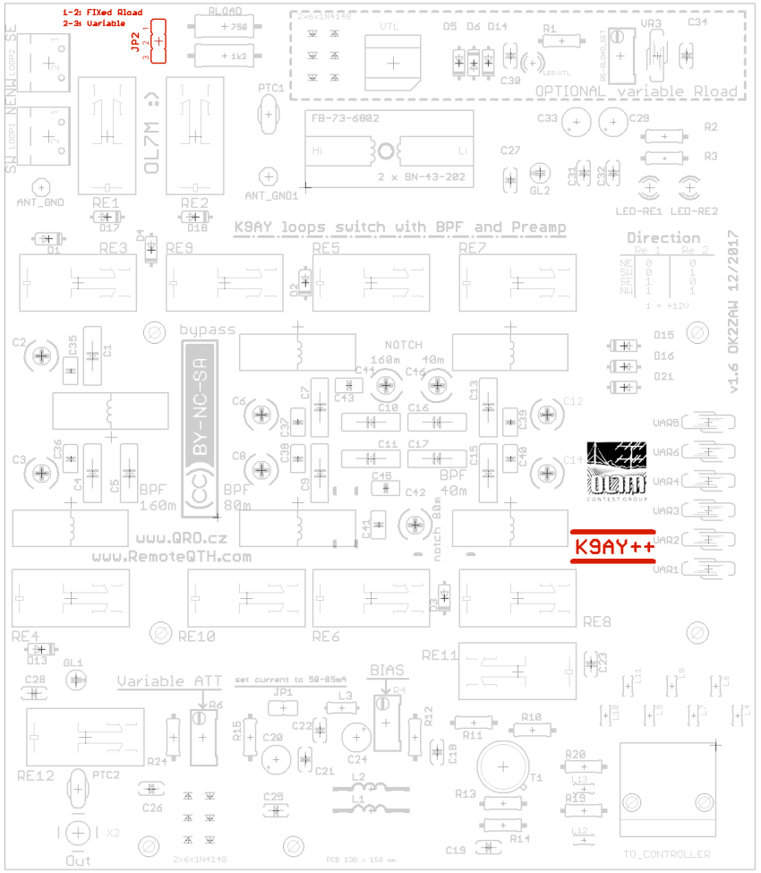
What is inside
- There is PCB in the feeder box which is assembled with Direction switch relays, Rload system (fixed and variable), Impedance transformer, Band Pass Filters, Preamplifier with Variable Attenuator, Protections and Common-mode filters.
Variable and Fixed Rload resistor
- Antenna Loop needs LOAD resistance at one side of the loop. It is connected between end of the loop ang ground. Size of the Load Resistance -Rload - depends on size of the loop and frequency. You can set optimal value what effect on SWR and F/B. It is not very critical and in the most cases you can switch to FIXed value.
Continue to Jumpers setting:
Connector description
- There is standart RJ45 (ETHERNET) connector with shielding. This is not LAN port!
- You can use cheap CAT-5 or CAT-6 cable up to 100m - FTP version - shielded
- Please read this instruction, use ONLY Copper wires
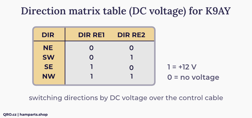
- direction switching matrix table ( apply +12V for logic 1 )
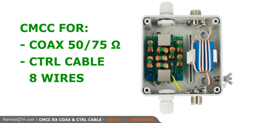
Common mode filter for coax and controller cable
OPTION
Common-mode choke coils work as a simple wire against differential mode current (signal), while they work as an inductor against common-mode current (noise). This box is designed as a common-mode filter for RF cable and also for analog AC/DC controller wires. This version is directly designed for K9AY++ antenna system.


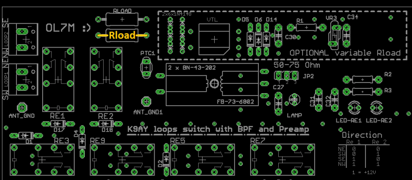
Rload FIXed or VARiable
- With Jumper JP2 you can switch between FIXed or VARiable Rload.
- If you short 1 and 2 than there is abt 450 Ohm fixed Rload. If you use controller with Rload controller, than switch to last position 9
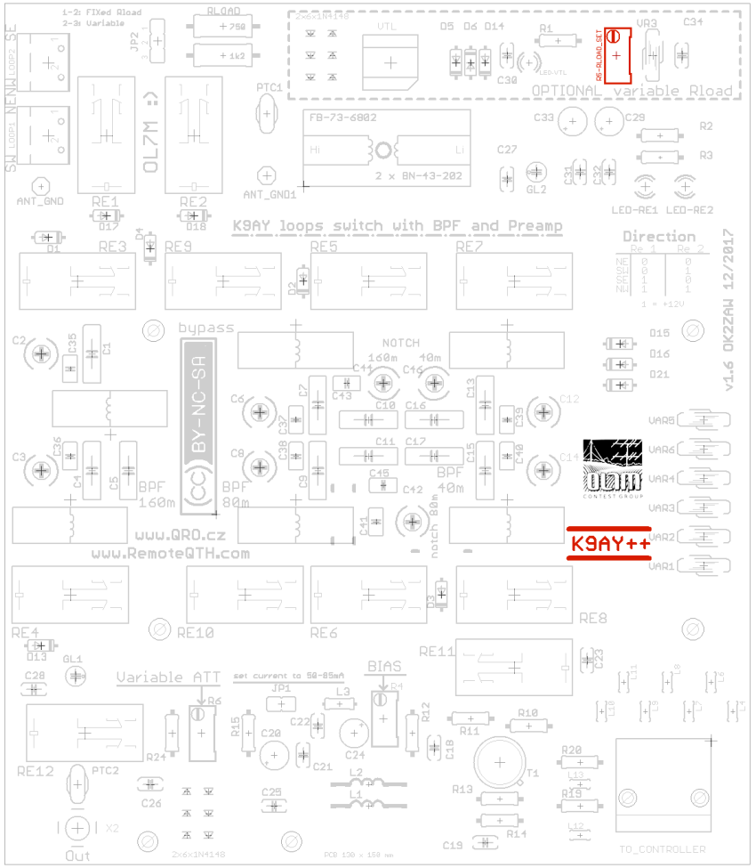
Rload checking the resistance
- This is function is only for K9AY feeder with Variable Rload part.
- There are two ways for fine tunning of Rload.
- Please check some more info about Controller box of K9AY++ on this link
- Connect Ohm meter to this position and measure value vs input Rload VTL voltage - PIN 6 on RJ45 connector
⚠ NOTE: Final Rload resistance may vary with the direction switching. This is caused by thin GND wire between controller and RF feeder box. If the changing is lower than 10 % than all is OK, if more, than more GND wires are recommended. Using CAT-5 FTP (shielded) cable can be big advantage in this problem.
⚠ NOTE: For final tunning and measuring, please connect control cable as well also the coax one!
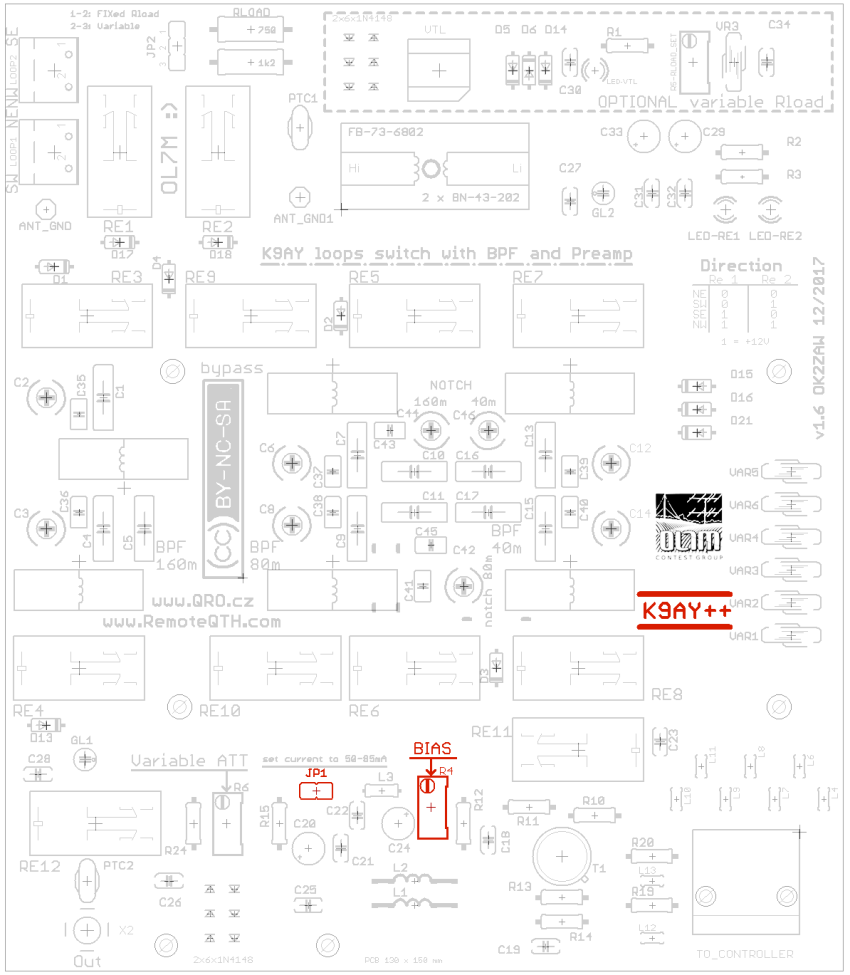
Preamp BIAS SET check current and voltage
- Connect Volt-meter to GND and jumper JP1. Measure voltage ( PREAMP ON ), it should be more than 11V. ( if you want HIGHer IP3, than it could be 13V / 60mA :) )
- DISconnect jumper JP1 and connect mA meter on the pins ( 200mA scale is fine ). Turn with R4 multi-turn trimmer and set bias to 45 - 65mA. You can have a look at my measurements: 2N5109 OIP3 vs voltage and bias
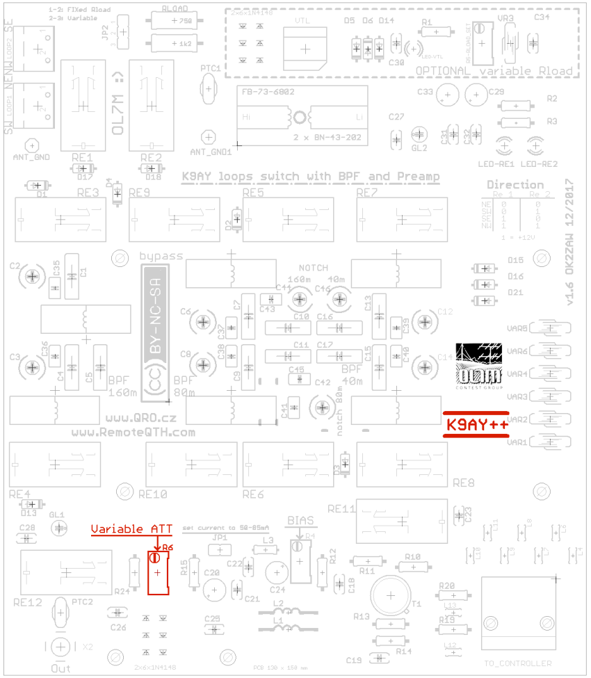
Preamp GAIN set
- Total gain of PREAMP is around 18 dB.
- With the trimmer R6 you can set gain as you need.
- There is variable ATT.
- Gain can be set from 0dB to about 18dB.
Direction switching check
- There are LEDs in the feeder box. You can check it easy there.
- Switching matrix is under LEDs.