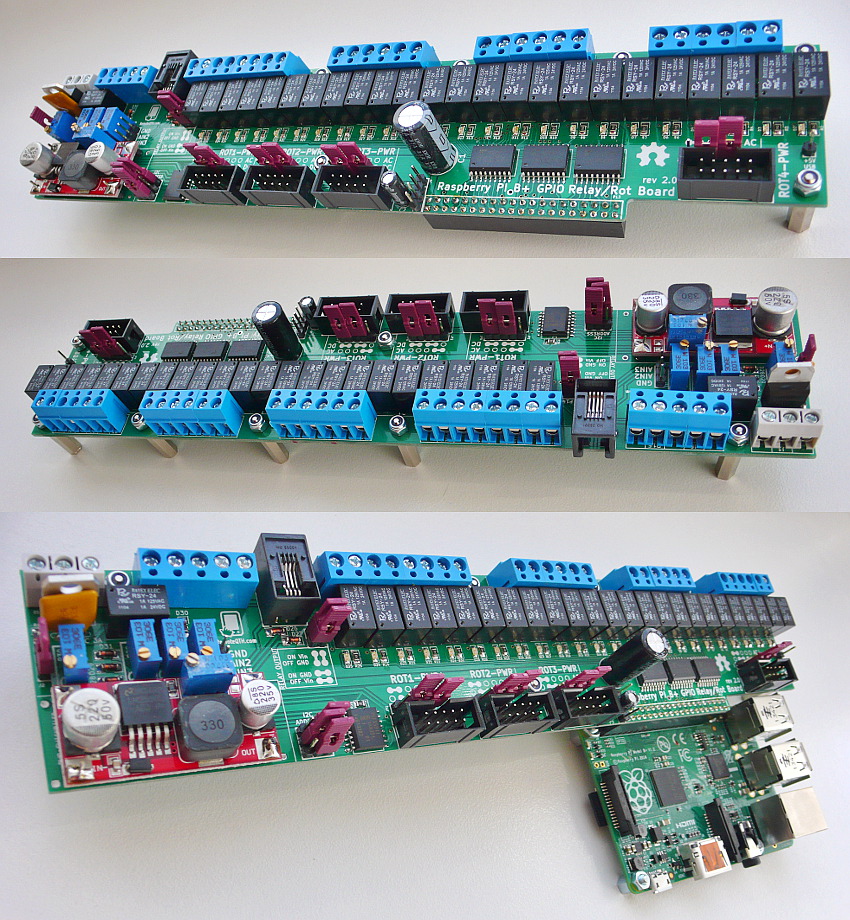
Raspberry PI2-B+ GPIO interface board 2.2
Specifications
- 24V Power supply.
- 24 Relay + LED, controlled from Rapsberry PI2/B+ GPIO
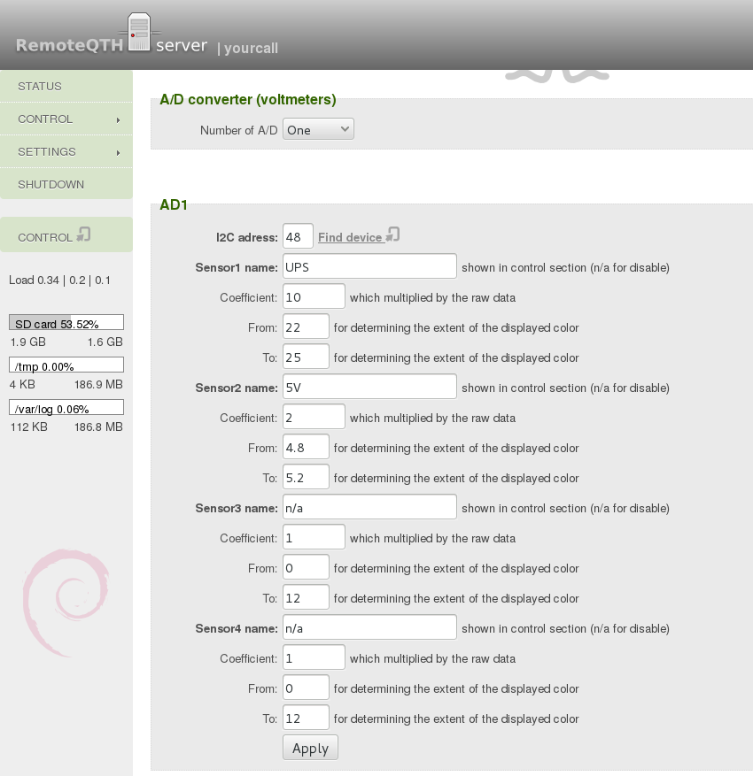
- A/D converter with 4 inputs.
- I2C output for connecting the temperature sensor.
- Conector for power and configure four Arduino rotator interface.
- The PCB size 5x25 cm
Schematics
Quik start guide
- Before connect power remove JP9 jumper from gpio board - switching the 5V power supply for RPI
- Power may be from two sources. If you use only one source, connect power to UPS input - this is monitoring internal A/D converter and LED on front panel.
- 24V DC from power supply
- 24V UPS from backup battery circuit
- If power stable connected, connect Ethernet cable with DHCP on router enable to RPI and short JP9 jumper - now running and boot RPI server - if you want to run without RPI server, remove the microSD card, and continue on point #6.
- Web interface IP addres will tell your dhcp server or any network scan, for example Fing
- Default login: yourcall, password: 1234
- Front panel power switch paralel connected to first relay on gpio board - rotators may be power ON localy or remotely via web interface
- Front panel LED signals power in UPS input
- Rotator modules work independently to RPI server - how configure Single rotator interface
- Web features configure via RemoteQTH-server
Have Fun!
Connectors
- J1 +24V DC Power
- J6 J15 - four rotator interface AC od DC Power
- J5 - RJ9 connector for other I2C temp sensors
- P16 - where the relay switch voltage on outs, here is voltage IN
- P1-P12 - GPIO Relay outputs
- J7-J10 - connect four rotator interface
Jumpers
- J2 - Power switch and LED
- J11 - two free A/D inputs
- I2C - set address A/D converter
- JP1-JP8 - preset power each rotator interface separately
- J4 - I2C bus
- J3 - switched +5V for USB hub
- Green 1-4 - measuring points input four A/D converters
Trimmer
- R27-R30 - voltage divider for A/D converter
RemoteQTH server presets
typycaly set A/D converter - It depends on the settings of the input voltage divider (Trimmer R27-R30)