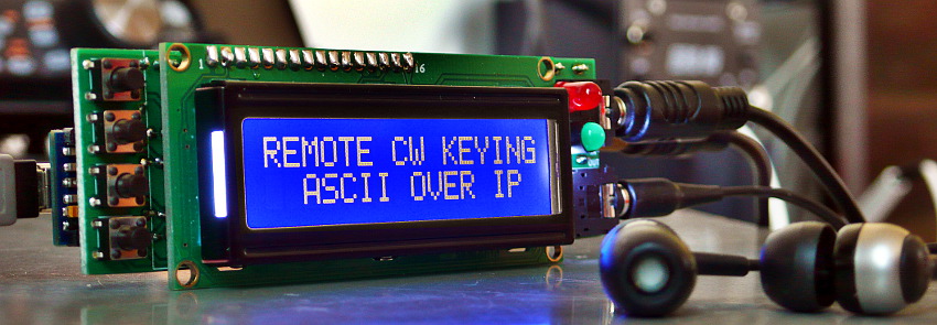
Local CW keyer for remote keying

Main functions:
- CW keying
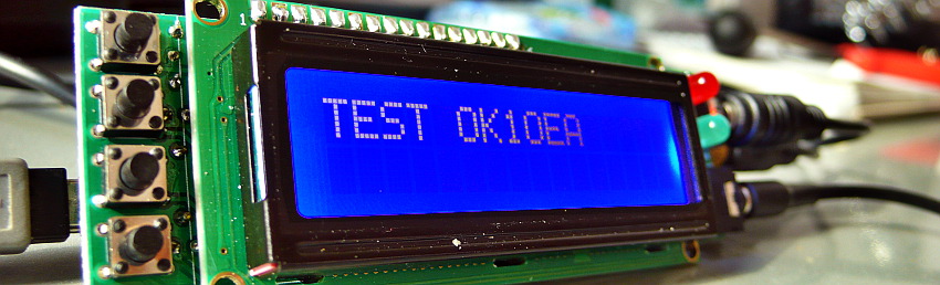
- Detect keying characters and show on the LCD
- Send keying characters to USB serial (echo mode)
- CW sidetone during the PTT is ON, otherwise play audio from RX
- Sidetone volume
- Four SET/MEM switch
Configure Arduino firmware
Master key
- Enable paddle echo in serial CLI with \*
- Or default in firmware. Find this line
byte cli_paddle_echo = 0;
and set from 0 to 1byte cli_paddle_echo = 1;
Slave key
- Disable sidetone \o
- Disable CW send echo in serial CLI with \:
- Or default in firmware. Find line
byte cw_send_echo_inhibit = 0;
and set from 0 to 1byte cw_send_echo_inhibit = 1;
- Disable send ? after error char - disable (abt line 4655)
//default: send_the_dits_and_dahs("..--..");break;and add new line between define other char (abt line 4617)case '?': send_the_dits_and_dahs("..--..");break;
Plug&play connecting in Linux
Udev rules
After connect Arduino nano show IDs with type dmesg in terminal, and edit udev rules
vim /etc/udev/rules.d/99-remoteqth.rules
SUBSYSTEM=="tty", ATTRS{idVendor}=="0403", ATTRS{idProduct}=="6001", ATTRS{serial}=="A702R984", SYMLINK+="ttyCW0", RUN+="/etc/cw.sh"
Connection script /etc/cw.sh
#!/bin/bash
SERVER=192.168.1.1  # IP YOUR SERVER
CWDPORT=6789
killall socat
sleep 3
socat UDP:$SERVER:$CWDPORT /dev/ttyCW0,raw,echo=0 &
exit 0
Connecting in Windows
Server side
Your need server (Raspberry PI) with CWdaemon, or next hardware arduino cw keyer connected via Ser2Net proxy.
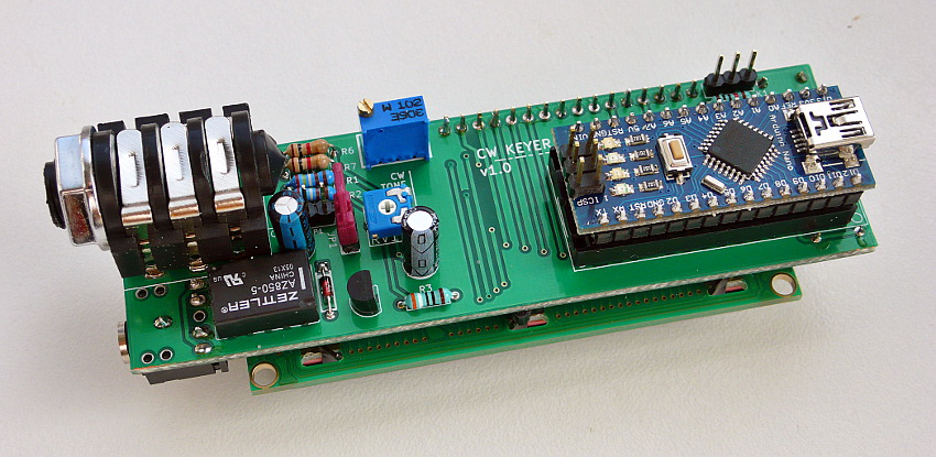
Assembly
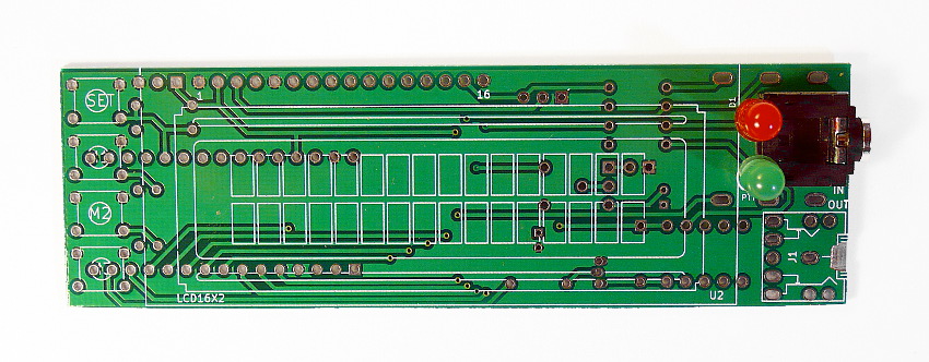
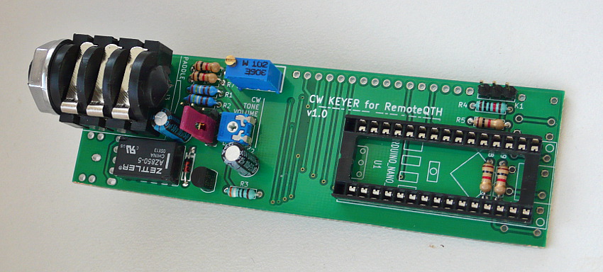
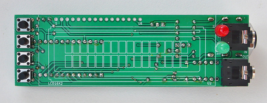
Circuit diagram
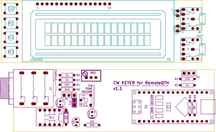
- Jumper JP1 choose output between headphone and external out on P1
- K1 prepared for connection CW speed potentiometer
- RV1 set CW sidetone volume
- RV2 preset LCD contrast
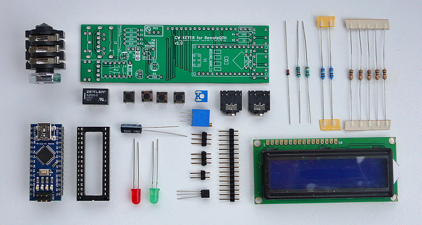
✔ Components
❏ Solder J2, D1, D2
❏ All parts of backside (C1 sign wrong polarity on PCB)
❏ J1, four TACT switch
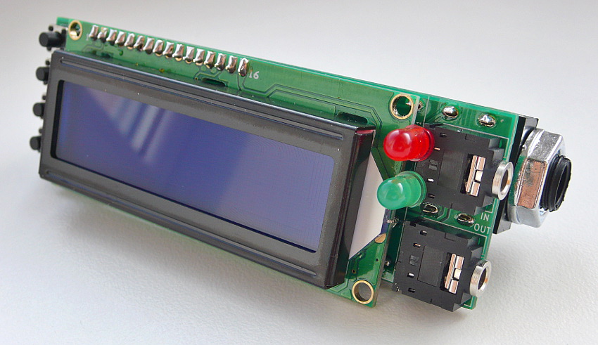
❏ LCD
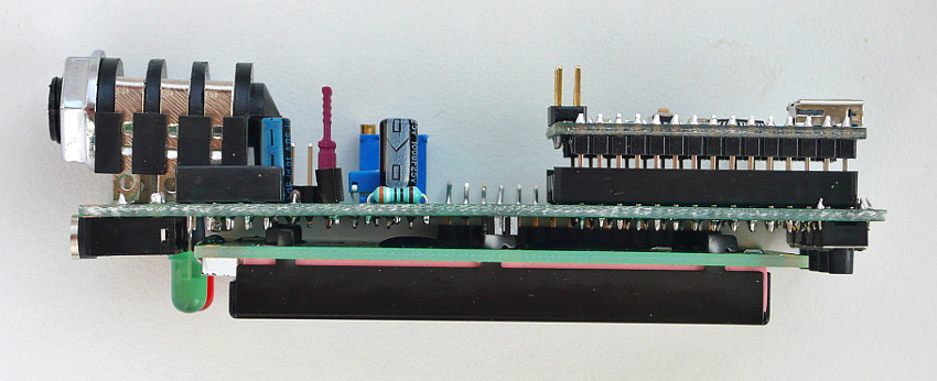
❏ Insert Arduino Nano